Sign In
Upload
Manuals
Brands
Woodward Manuals
Control Unit
505XT
Woodward 505XT Digital Control System Manuals
Manuals and User Guides for Woodward 505XT Digital Control System. We have
3
Woodward 505XT Digital Control System manuals available for free PDF download: Installation And Operation Manual, Product Manual
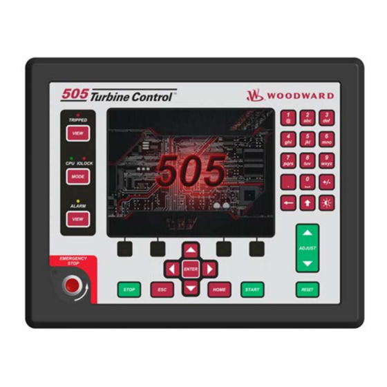
Woodward 505XT Installation And Operation Manual (242 pages)
Digital Control for Steam Turbines
Brand:
Woodward
| Category:
Control Unit
| Size: 8.13 MB
Table of Contents
Table of Contents
3
Warnings and Notices
8
Electrostatic Discharge Awareness
10
Regulatory Compliance
11
Chapter 1. General Information
16
Introduction
16
Controller Overview
16
Figure 1-1. Typical Single or Dual Inlet Steam Turbine
18
Figure 1-2. Typical Extraction And/Or Admission Steam Turbine
18
Functional Block Diagrams
19
Figure 1-3. Explanation of Symbols
20
Figure 1-4. Single or Split-Range Turbine Configurations
20
(Valve Demand Overview)
20
505 Inputs and Outputs
21
Figure 1-5. Turbine Configurations Using Extraction And/Or Admission
21
(Valve Demand Overview)
21
Table 1-2. Selectable Functions for Discrete Inputs
22
Table 1-3. Selectable Functions for 4-20Ma Analog Outputs
23
Table 1-4. Selectable Functions for Relay Output States
24
Optional Distributed I/O
25
Figure 1-6. Linknet Distributed I/O Node
25
Figure 1-7. Vibration Wizard for Linknet Node 1
26
Figure 1-8. Linknet Node 1 with 4 Vibration Signals
26
Figure 1-9. Vibration Monitoring Page
27
Keypad and Display
28
Figure 1-10. 505 Keypad and Display
28
Watchdog Timer/Cpu Fault Control
29
Chapter 2. Hardware Specifications
30
Flex505 Description and Features
30
Figure 2-1. Functional Block Diagram (505 Control)
30
Environmental Specifications
31
Maintenance Info and Recommendations
31
Electromagnetic Compatibility (EMC)
32
Outline Drawing for Installation
32
Figure 2-2. 505D Outline Drawing
33
Input Power Specification
34
Visual Indicators (Led's) & CPU Configuration
34
Communications (Ethernet)
35
Communications (CAN)
36
Table 2-3. CAN Specifications
37
Specifications
38
Communications (Service Ports)
39
Figure 2-3. COM1 Example RS-485 Wiring
39
Hardware - Terminal Blocks & Wiring
40
Figure 2-4. 505 Back Cover Label
40
Terminal Block Connectors
41
Hardware - Speed Sensor Inputs
41
Figure 2-5. Terminal Block Connectors
41
Figure 2-6. Speed Sensor Block Diagram
42
Hardware - Analog Inputs (4-20 Ma)
43
Figure 2-7. Analog Input - Self-Powered Block Diagram
43
Hardware - Analog Outputs (4-20 Ma)
44
Figure 2-8. Analog Input - Loop-Powered Block Diagram
44
Hardware - Actuator Outputs
45
Figure 2-9. Analog Output Block Diagram
45
Hardware - Discrete Inputs
46
Figure 2-10. Actuator Output Block Diagram
46
Figure 2-11. Discrete Input Block Diagram
46
Hardware - Relay Outputs
47
Figure 2-12. Relay Output Block Diagram
47
Troubleshooting Fault Codes
48
Troubleshooting & Commissioning Checks
48
Chapter 3. 505XT Control Description
51
Introduction
51
Turbine Start Modes
51
Start Permissive
52
Open Wire Detection on MPU Speed Signals
52
Zero Speed Signal Override
52
Figure 3-1. Open Wire Detection Test
52
Direction of Rotation Detection
53
Figure 3-2. Speed Input Channel - Phase Difference
53
Detecting Zero Speed
54
Manual Speed Override
54
Figure 3-3. Speed Probe Rotation Check
54
Figure 3-4. Speed Probe Zero Speed Detect
54
Automatic Speed Override
55
Acceleration Limiter
55
Turbine Start Mode Procedures
55
Figure 3-5. Manual Start Mode Example
56
Figure 3-6. Semiautomatic Start Mode Example
57
Figure 3-7. Automatic Start Mode Example
58
Figure 3-8. Idle/Rated Start
60
Figure 3-9. Automatic Start Sequence
61
Table 3-2. Hot and Cold Parameter Interpolation Rates and Delays
62
Table 3-3. All Required Conditions, if Configured, for a Warm or Hot Start
63
Speed Control Overview
65
Speed PID Operational Modes
66
Figure 3-10. Speed Control Functional Diagram
66
Figure 3-11. Speed PID Control Modes
68
Figure 3-12. Frequency and Unit Load Relationship
69
Figure 3-13. Speed Relationships
71
Table 3-4. Frequency Arm/Disarm Generator Control Modes
73
Figure 3-14. Load Sharing Logic
77
Manual Demand
78
Load Rejection
79
Feed-Forward Input
79
Cascade Control
81
Figure 3-15. Typical Anti-Surge Valve and Speed Feed-Forward Logic Trend
81
Figure 3-16. Cascade Functional Diagram
82
Auxiliary Control
86
Figure 3-17. Aux Control Overview
86
Remote Auxiliary Set Point
89
Extraction/Admission Control
91
Figure 3-18. Extraction/Admission Control Overview
91
Figure 3-19. Transitions between Speed Only and Ratio Limiter Control - Auto Mode
93
Figure 3-20. Transitions between Speed Only and Ratio Limiter Control - Manual
94
Figure 3-21. Extraction/Admission Control Panel
95
Steam Performance Map Menu
97
Figure 3-22. Typical Extraction Steam Map
100
Figure 3-23. Typical Admission Steam Map
102
Figure 3-24. Typical Extraction & Admission Steam Map
103
Table 3-7. Alternate Modes for Ext/Adm Turbines
104
Figure 3-32. Ext/Adm Mode Control Priorities
109
Inlet Steam Pressure Control
110
Figure 3-33. Configured for Full Decoupled Mode (no Map)
110
Exhaust Steam Pressure Control
111
Figure 3-34. Inlet Steam Pressure Control Overview
111
HP Valve Limiter
112
Figure 3-35. Exhaust Steam Pressure Control Overview
112
LP Valve Limiter
113
Manual Valve Demand
113
Inlet Steam Pressure Compensation
114
Isolated PID Control
114
Emergency Shutdown
115
Controlled Shutdown
116
Overspeed Test Function
117
Local/Remote Function
117
Table 3-8. Exceptions to Local Mode Contact Input and Modbus Command Disabled
118
Relays
119
Chapter 4. Configuration Procedures
121
Program Architecture
121
Display Modes and User Levels
121
Configuring the 505XT
122
Figure 4-1. Initial HOME Screen (Unit Not Configured)
122
Figure 4-2. Configuration Menu - Configuration Mode (Edit)
124
Exiting the Configure Mode
151
Table 4-3. Configuration Error Messages
152
Valve/Actuator Calibration & Test
159
Calibration/Stroking Procedure
159
Chapter 5. 505 Operation
161
Software Architecture
161
Power-Up Screen
161
Figure 5-1. Software Architecture
161
Figure 5-2. 505 Splash Screen
162
Figure 5-3. Boot-Up to HOME Screen
162
Control Mode Architecture
163
Figure 5-4. Control Mode Architecture
163
User Login Levels
164
Figure 5-5. Mode Screen
164
Navigation
165
Page Organization
165
Figure 5-6. Navigation Cross
165
Figure 5-7. Service Menu Showing "Speed Control" IN-Focus
165
Figure 5-8. Configuration Menu - Operation Mode (View Only)
166
Figure 5-9. Configuration Menu - Configuration Mode (Edit)
166
Overview Screen
167
Speed Control Screen
167
Figure 5-10. Overview Screen
167
Figure 5-11. Speed Control Screen
167
Valve Demand Screen
168
Figure 5-12. Valve Demand Screen
168
Controllers Screen
169
Cascade Control Screen
169
Figure 5-13. Controllers Screen
169
Figure 5-14. Cascade Control Screen
169
Auxiliary Control Screen
170
Inlet Control Screen
170
Figure 5-15. Auxiliary Control Screen
170
Figure 5-16. Inlet Steam Pressure Control Screen
170
Extraction/Admission Control Screen
171
Figure 5-17. Ext/Adm Pressure Control Screen
171
Exhaust Control Screen
172
Steam Map Screen
172
Figure 5-18. Exhaust Pressure Control Screen
172
Figure 5-19. Steam Map Screen
172
Analog Input Summary Screen
173
Figure 5-20. Steam Map - Mode Popup
173
Figure 5-21. Analog Input Summary Screen
173
Contact Input Summary Screen
174
Analog Output Summary Screen
174
Figure 5-22. Contact Input Summary Screen
174
Figure 5-23. Analog Output Summary Screen
174
Relay Output Summary Screen
175
Actuator Driver Summary Screen
175
Figure 5-24. Relay Output Summary Screen
175
Figure 5-25. Actuator Driver Summary Screen
175
Starting Procedures (Start Curve Screen)
176
Figure 5-26. HOME Menu Showing "Startup Curve" IN-Focus
176
Overspeed Test Function (Speed Control Screen)
177
Figure 5-27. Overspeed Test Permissives
177
Figure 5-28. Internal (505) Overspeed Test
178
Figure 5-29. External Overspeed Test
178
Stop Key
179
Alarm Summary
179
Figure 5-30. ALARM Screen
179
Table 5-1. ALARM Messages
180
Shutdown Summary
183
Figure 5-31. Shutdown Summary Screen
183
Manual Dynamic Adjustments of Speed, Cascade, Auxiliary, Inlet, Exhaust and Ext/Adm Controls
185
Figure 5-32. Speed Dynamics Adjustment Screen
185
Figure 5-33. Typical Response to Load Change
188
Figure 5-34. Overview of the Automated PID Optimizer Routine
189
Figure 5-35. Optimization Routine Overview Trend
190
Figure 5-36. Configuration Parameters 'Configure' Pop-Up
191
Chapter 6. Communications
198
Modbus Communications
198
Figure 6-1. ASCII/RTU Representation of 3
199
Table 6-2. Modbus Frame Definition
200
Port Adjustments
201
505 Control Modbus Addresses
201
Table 6-7. Boolean Write Addresses
202
Table 6-8. Boolean Read Addresses
203
Table 6-9. Analog Read Addresses
210
Table 6-10. Analog Write Addresses
215
Table 6-12. Analog Read Register (3:0234) Control Status
216
Table 6-14. Analog Read Register (3:0236) Map Limiter Status Messages
217
Table 6-17. Analog Output Configuration
218
Table 6-18. Relay Configuration – for Level Switches
219
Table 6-19. Relay Configuration – for State Indications
220
Table 6-20. Contact Input Configurations
221
Specific Address Information
222
Chapter 7. Product Support and Service Options
224
Product Support Options
224
Product Service Options
224
Returning Equipment for Repair
225
Replacement Parts
226
Engineering Services
226
Contacting Woodward's Support Organization
226
Technical Assistance
227
Appendix A. 505Xt Configuration Mode Worksheets
228
Revision History
239
D Eclarations
240
Advertisement
Woodward 505XT Product Manual (176 pages)
Digital Controlfor Steam Turbines (Single valve, Extraction and/or Admission)
Brand:
Woodward
| Category:
Controller
| Size: 7.31 MB
Table of Contents
Table of Contents
3
Warnings and Notices
8
Electrostatic Discharge Awareness
9
Introduction
10
Chapter 8. Service Tools
11
Overview
11
Control Assistant (CA)
11
Servlink-To-OPC-Server (SOS)
11
Appmanager (Appman)
11
505 Remote View
12
Chapter 9. Peripheral Devices
13
Overview
13
DSLC-2 (Generator Synchronizer and Load Control)
13
Figure 9-1. DSLC-2
13
Figure 9-2. Configuration/Woodward Links/Dslc-2
14
Figure 9-3. Service Screen - DSLC-2 Power Parameters
14
Figure 9-4. Service Screen - DSLC-2 Status Parameters
15
Varistroke II (Electro-Hydraulic Actuator)
16
Figure 9-5. VS-II
16
Figure 9-6. Configuration/Woodward Links/Vs-II
16
MFR300 (Multi-Function Relay)
17
Figure 9-7. Service/Varistroke II
17
Figure 9-8. MFR300 Multi-Function Relay
17
Figure 9-9. Configuration/Woodward Links/Mfr300
18
Figure 9-10. Service Screen1/Woodward Links/Mfr300
18
Protection/Breaker Control Relay)
19
Figure 9-11. Service Screen2/Woodward Links/Mfr300
19
Figure 9-12. LS-5
19
Figure 9-13. Configuration/Woodward Links/Ls-5
20
Highprotec (Generator Protection Unit)
21
Figure 9-14. Service Screen/Woodward Links/Ls-5
21
Figure 9-15. Highprotec
21
Servo Position Controller (SPC)
22
Figure 9-16. Configuration Screen/Woodward Links/Highprotec
22
Figure 9-17. Service Screen/Woodward Links/Highprotec
22
Real Power Sensor
23
Figure 9-18. Servo Position Controller
23
Figure 9-19. Interface to Servo Position Controller
23
Engine Generator Control Package/Load Sharing (EGCP-3 LS)
24
Figure 9-20. Real Power Sensor
24
Figure 9-21. EGCP-3 Control
25
Figure 9-22. EGCP-3 LS Functional Diagram
26
Figure 9-23. EGCP-3 LS Interface Wiring
27
Applying the 505 with Redundant I/H or I/P Converters
28
Figure 9-24. Typical Redundant I/H System with a Transfer Valve
28
Figure 9-25. Typical Redundant I/P System with a Pressure Selecting Relay Valve
29
Chapter 10. Application Notes
30
Overview
30
Example Applications
32
Example 1-Pump or Compressor Discharge Pressure Control with Turbine Inlet Pressure Limiting
33
Figure 10-1. Pump or Compressor Discharge Pressure Control with Turbine Inlet Pressure Limiting
33
Example 2-Inlet Pressure Control with Automatic Synchronizing & Generator Power Limiting
36
Figure 10-2. Inlet Pressure Control with Automatic Synchronizing & Generator Power Limiting
36
Example 3-Exhaust Pressure Control with Generator Power Limiting and Plant Import/Export Limiting
40
Figure 10-3. Exhaust Pressure Control with Generator Power Limiting and Plant Import/Export Limiting
40
Example 4-Plant Import/ Export Control with SPC Servo Interface
43
Figure 10-4. Plant Import/Export Control with SPC Servo Interface
44
Example 5-Inlet Pressure Control with Isochronous Load Sharing Control in Island Mode
47
Figure 10-5. Inlet Pressure Control with Isochronous Load Sharing Control in Island Mode
48
Example 6-Import/Export Control or Exhaust Pressure Control with Isoch Load Sharing in Island Mode
51
Figure 10-6. Import/Export Control or Exhaust Pressure Control with Isoch Load Sharing in Island Mode
51
Example 7-Induction Generator Applications
54
Example 8 - Extraction Turbine Mechanical Drive (Pump or Compressor) with Discharge Pressure Control and Turbine Inlet Pressure Limiting
55
Figure 10-7. Pump or Compressor with Discharge Pressure Control and Turbine Inlet Pressure Limiting
55
Example 9 - Extraction Turbine Inlet and Extraction Pressure Control with Automatic Synchronizing & Generator Power Limiting
59
Figure 10-8. Inlet Pressure Control with Automatic Synchronizing & Generator Power Limiting
59
Chapter 11. Operator Interface
64
Introduction
64
Graphical Display and Key Inputs
64
Figure 11-1 505 Keypad and Display
64
Service Panel Modes and User Levels
65
Chapter 12. Service Menu Procedures
67
Overview
67
Using the Service Menus
67
Figure 12-1. User Login for Service
67
Figure 12-2. Authorized and Unauthorized Components
67
Figure 12-3 Service Menu
68
Figure 12-4 Service Menu
69
Service Mode Parameters
71
Chapter 13. Understanding Pid Settings
101
Overview
101
Proportional Response
102
Figure 13-1. Proportional Gain Setting Effects
102
Proportional + Integral (Closed Loop)
103
Figure 13-2. Open Loop Proportional and Integral Response
103
Figure 13-3. Closed Loop Proportional and Integral Response
104
Derivative Response
105
Figure 13-4. Integral Gain (Reset) Setting Responses
105
Proportional + Derivative (Closed Loop)
106
Figure 13-5. Closed Loop Proportional and Derivative Action
106
Proportional + Integral + Derivative (Closed Loop)
107
Figure 13-6. Derivative Setting Effects
107
Figure 13-7. Closed Loop Proportional, Integral and Derivative Action
108
Controller Field Tuning General
109
Figure 13-8. Typical Response to Load Change
109
OPTI_PID Automatic Dynamic Optimizer
110
Figure 13-9. Speed Dynamics for Extraction/Admission Type Turbine
110
Figure 13-10. Speed Dynamics Generator On-Line Gain Curve
111
Figure 13-11. Speed Dynamics Optimizer
112
Figure 13-12. Configuring Settings for Opti_Tune
113
Chapter 14. Hardware/Operating System Faults
114
General
114
Wiring Problems
114
Control Adjustments
114
Other Operating Problems
115
505 Design Specifications
116
Hardware Specifications
116
Software Specifications
116
505Xt Service Mode Worksheet
118
Appendix D. Password Information
133
General
133
Monitor User Level
133
Operator" User Level Password
133
Service" User Level Password
133
Configure" User Level Password
133
Serviceuser" User Level Password
133
Appendix E. Servlink-To OPC Server (SOS) Tool
134
SOS Communication Link
134
Installing SOS
134
Figure E-1. SOS
134
Connecting a Pc/Laptop to the Control
135
Figure E-2. SOS Install Window
135
Figure E-3. SOS Server Status Dialog Box
135
Figure E-4. SOS - New Session Box
136
Figure E-5. SOS - Enter 505 TCP/IP Address
136
Figure E-6. SOS - Active Links Dialog Box
136
Appendix F. Control Assistant-Software Interface Tool
138
Features of Control Assistant
138
Installing Control Assistant
138
Figure F-1. Control Assistant License Agreement
138
Figure F-2. Control Assistant Install Window
139
Figure F-3. Control Assistant Folder Selection
139
Figure F-4. Control Assistant Install Complete
139
Using Control Assistant
140
Figure F-5. Install Restart Window
140
Figure F-6. Control Assistant Window
140
Figure F-7. Dialog for Servlink OPC Connection
141
Figure F-8. Winpanel Session
141
Figure F-9. Control Assistant - Retrieve Tunable Dialog Box
142
Figure F-10. Control Assistant - Send Tunable Dialog Box
143
Figure F-11. Control Assistant - Speed Control Trend Script
144
Figure F-12. Control Assistant - Create Trend Script File
144
Appendix G. Appmanger Service Tool
145
File Management with App. Manager
145
Installing App Manager
145
Figure G-1. App Manager Install Window
145
Figure G-2. App Manager License Agreement Window
146
Figure G-3. App Manager Installation
146
Figure G-4. App Manager Install Complete
146
Figure G-5. Appmanager Window
147
Figure G-6. Dialog for App Manager Connection
147
Figure G-7. App Manager Connected to a Control
148
Figure G-8. Appmanager Control Info Window
148
Figure G-9. Appmanager Control (GAP) Application Panel
149
Figure G-10. Appmanager GUI Application Panel
149
Figure G-11. Retrieving Files
149
Appendix H. Configuring Network Tcp/Ip Addresses
152
Figure H-1. Configuration/Communications Screen
152
Figure H-2. Ethernet Port Layout (Ports on Side)
152
Setting SNTP ("Simple Network Time Protocol")
154
Figure H-3. Real Time Clock SNTP Settings
154
Appendix I. Remoteview Tool
155
Figure I-1. Window Shown When the Time Limit Is Exceeded
155
Figure I-2. Installation Welcome Window
155
Figure I-3. Installation Folder Window
156
Figure I-4. Installation License Agreement Window
156
Figure I-5. Installation Start Menu Shortcuts Window
157
Figure I-6. Installation Ready to Install Window
157
Figure I-7. Installation Complete Window
158
Figure I-8. Entering an IP Address to be Added to the Control List
158
Figure I-9. Control Selected in the Control List
159
Figure I-10. Login Window with Fields for User Name and Password
159
Figure I-11. an Application Selected in the Application List
160
Figure I-12. Default View of the Tool
161
Figure I-13. Simple View of the Tool
161
Figure I-14. Full View of the Tool
162
Figure I-15. Entering a Name for the Current Settings
162
Figure I-16. a New Settings File Entered in the Predefined Settings List
163
Figure I-17. Remote View Tool (Default Setting) after Opening from the Configuration Window
164
Appendix J. Using 505 Internal Simulation Mode
165
Figure J-1. HW Simulation Mode Access
165
Appendix K. Custom Tag Name Procedure
166
Appendix L. Startup Guide
167
Commissioning Checklist
167
Appendix M. Datalogs
169
Overview
169
Figure M-1. the Datalog Service Menu Page
170
Figure M-2. Datalog Graph Properties
171
Figure M-3. Datalog Plot
172
Figure M-4. Automated File Collection Configuration
173
Figure M-5. Automated File Collection Active
174
Revision History
175
Woodward 505XT Product Manual (115 pages)
Digital Control for Steam Turbines, Single Valve, Extraction and/or Admission
Brand:
Woodward
| Category:
Control Unit
| Size: 4.25 MB
Table of Contents
Table of Contents
3
Warnings and Notices
6
Electrostatic Discharge Awareness
7
Chapter 15. General Information
8
Figure 15-1. Typical Redundant 505XT Application Configuration
9
Feature Differences between the 505DR and Previous 505/505XT
10
Chapter 16. Redundant Setup and Configuration
11
Hardware Setup
11
Input and Output Signals
12
Figure 16-1. 505DR with FTM
12
Actuator Drivers
16
Figure 16-2. Single Coil Shared Driver
17
Figure 16-3 Single Coil Shared Driver with 505DR FTM
17
Figure 16-4 Dual Coil Driver
18
Figure 16-5. Dual Coil Driver with 505DR FTM
18
Figure 16-6. Redundant (Parallel) Actuator Driver
19
Figure 16-7. Redundant (Parallel) Actuator Driver with 505DR FTM
19
Figure 16-8. Actuator Driver with Redundant Demands
20
Figure 16-9. Actuator Type Configuration
23
Figure 16-10. Driver Channel Configuration
24
Figure 16-11. Ma Backup Channel Configuration
25
CAN Devices - Optional I/O and Digital Drivers
26
Figure 16-12. Driver Configuration Page Buttons
26
Figure 16-13. Servo Position Controller
27
Figure 16-14. SPC Driver CAN Links
28
Figure 16-15A. SPC Driver Configuration for Redundant Actuators
29
Figure 16-15B. SPC Driver Configuration for Redundant Actuators
30
Figure 16-15C. SPC Driver Configuration for Redundant Actuators
31
Figure 16-15D. SPC Driver Configuration for Redundant Actuators
32
Figure 16-15E. SPC Driver Configuration for Redundant Actuators
33
Figure 16-15F. SPC Driver Configuration for Redundant Actuators
33
Figure 16-15G. SPC Driver Configuration for Redundant Actuators
34
Figure 16-16A. SPC Driver Configuration for Dual Coil Actuators
34
Figure 16-16B. SPC Driver Configuration for Dual Coil Actuators
35
Figure 16-17. Expandable I/O Node 26 Driver (Bumpless SYSCON Transfer)
37
Communications
38
Figure 16-18. Single Network Modbus Architecture
38
Figure 16-19. Redundant Network Modbus Architecture
38
Configuration Menu
39
Service Menu
60
Calibration
61
Chapter 17. Redundant Operation
62
Initializing a Redundant System
62
Figure 17-1. Wait Run Permissive Screen
63
System Diagnostics
64
Figure 17-2. Navigating to the DR Overview Screen
64
Figure 17-3. System Diagnostics Screen
66
The SYSCON Unit
67
Figure 17-4. Primary/Secondary SYSCON/BACKUP Indications
67
Figure 17-5. Front Panel CPU LED SYCON/BACKUP Indication
68
The BACKUP Unit
70
Figure 17-6. SYSCON I/O Monitoring Pages
70
Figure 17-7. BACKUP Unit Available Screen
71
Figure 17-8. BACKUP Unit Inhibited Screen
72
Figure 17-9. BACKUP I/O Monitoring Menu
73
Figure 17-10 BACKUP Analog Inputs Screen
74
Figure 17-11. BACKUP Speed Inputs Screen
74
Figure 17-12. BACKUP Analog Outputs Screen
75
Figure 17-13. BACKUP Actuator Outputs Screen
76
Figure 17-14. BACKUP Boolean Inputs Screen
77
Figure 17-15. BACKUP Relay Outputs Screen
77
Operational Commands and Settings
78
Online Unit Repairs
79
Figure 17-16. User SYSCON Transfer Command
79
Figure 17-17. User Unsync Backup Command
80
Figure 17-18. User Reset Backup Command
80
Figure 17-19. System Diagnostic Faults Cleared
81
Remoteview Connections
82
Figure 17-20. BACKUP Available
82
Figure 17-21. Session Connections Dialog Box
83
Failover Performance
84
Figure 17-22. Actuator Output Failover Performance
84
Figure 17-23. Rtcnet Node 26 Analog Output Performance
84
Alarms
85
Figure 17-24. SPC Analog Output Performance
85
Trips
94
Modbus Addressing
96
Revision History
114
Advertisement
Advertisement
Related Products
Woodward TecJet 50
Woodward 5448-882
Woodward 5448-880
Woodward 5448-881
Woodward TecJet 52 Gen II
Woodward MicroNet 5437-1104
Woodward MicroNet 5437-1105
Woodward MicroNet 5437-1106
Woodward MicroNet 5437-1107
Woodward 505
Woodward Categories
Controller
Control Unit
Relays
Control Systems
Industrial Equipment
More Woodward Manuals
Login
Sign In
OR
Sign in with Facebook
Sign in with Google
Upload manual
Upload from disk
Upload from URL