Sign In
Upload
Manuals
Brands
WinGD Manuals
Engine
X92-B
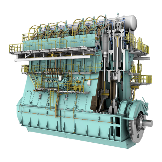
WinGD X92-B Manuals
Manuals and User Guides for WinGD X92-B. We have
1
WinGD X92-B manual available for free PDF download: Operation Manual
WinGD X92-B Operation Manual (460 pages)
Brand:
WinGD
| Category:
Engine
| Size: 12.08 MB
Table of Contents
Table of Contents
3
Operation Manual - Change Record
18
Change Record
18
Preface
20
Technical Documentation Set
22
Data Module Codes (Descriptive Data)
24
Data Module Codes (Procedural Data)
26
About this Book
28
About the Engine
30
Side View (Generic)
31
Engine Numbering (Generic)
32
List of Abbreviations
34
List of Abbreviations and Acronyms
34
Safety
39
Safety Precautions and Safety Guidelines
40
Contamination and Fire in the Scavenge Air Spaces
46
Fire-Fighting in the Scavenge Air Space
48
Explosions in the Crankcase
50
Prevent Explosions in the Crankcase
52
Access to Engine Spaces
54
Design and Function of the Engine
57
Short Description of the Engine
58
Pressure - Volume Diagram and Schematic of the Two-Stroke Diesel Cycle
59
Use of the Engine
60
Operating Range
60
Tuning Options
62
The Relation between Engine and Propeller
64
Schematic Diagram - Relation Speed/Power (FPP)
65
Operation
66
Design and Function of Systems
67
General for Systems
68
Line Codes for Systems
68
Line Codes
68
Cooling Water System
70
Cooling Water System (Generic and Simplified)
71
Wash-Water System
72
System Oil System
74
System Oil System (Generic and Simplified)
75
Servo Oil System
76
Servo Oil System (Generic and Simplified)
77
Cylinder Oil System
78
Cylinder Oil System (Generic and Simplified, with and Without Icat)
79
Starting Air System
80
Starting Air System (Generic and Simplified)
81
Scavenge Air System
82
Control Air System
84
Control Air System (Generic and Simplified)
85
Exhaust Gas System
86
Fuel System
88
Fuel System with FLV (Generic and Simplified)
90
Fuel System with ICU (Generic and Simplified)
91
LP Selective Catalytic Reduction System
92
LP SCR Temperature Controlled (Example)
93
LP SCR Bypass Rate Controlled (Example)
94
LP SCR Control System Layout
96
LP SCR System - Principal Control Configuration
97
Control Box E70 with Option SPC
98
Control Box E71 with Option SPC
99
Control Boxes E72 and E73
100
Lp Scr System Status (Main Page)
101
Page - LP SCR SYSTEM STATUS (MAIN PAGE)
101
Lp Scr System Overview
102
LDU-20 Page - LP SCR SYSTEM OVERVIEW
102
Lp Scr Interfaces
103
LDU-20 Page - LP SCR INTERFACES
103
Lp Scr Software Info
104
LDU-20 Page - LP SCR SOFTWARE INFO
104
Lp Scr Page Index
105
Page - LP SCR
105
Steam Production Control System
106
Example of SPC
106
LDU-20 Page - STEAM PRODUCTION CONTROL
107
LDU for the Steam Boost Mode
109
Design and Function of Components
111
Group 1 - Engine Frame and Bearings Bedplate
114
Main Bearing
116
Main
116
Main Bearing (Generic)
116
Thrust Bearing
118
Thrust Bearing (Generic)
119
Monoblock Column
120
Tie Rod
122
Group 2 - Cylinder Cylinder Liner
124
Cylinder - Cooling Water Outlet (Generic)
124
Lubricating Quill
126
Piston Rod Gland
128
Direct Controlled Injection Valve
130
Starting Valve
132
Exhaust Valve
134
Exhaust Valve (Generic)
134
Group 3 - Crankshaft, Connecting Rod and Piston Crankshaft
136
Torsional Vibration Damper
138
Axial Vibration Damper
142
Axial Vibration Damper (Generic)
142
Turning Gear
144
Connecting Rod and Connecting Rod Bearing
146
Connecting Rod and Connecting Rod Bearing (Generic)
146
Crosshead and Guide Shoe
148
Piston
150
Group 4 - Supply Unit Drive and Control Components Supply Unit Drive
152
Starting Air Shut-Off Valve
154
Starting Air Shut-Off Valve (Example)
154
Control Air Supply
156
Control Air Supply (Generic)
156
Local Maneuvering Stand for UNIC
158
Pick-Up for Speed Measurement
160
Group 5 - Supply Unit, Pumps and Control Valves Servo Oil Pump
162
Supply Unit
164
Fuel Pump
166
Fuel Pump - Cross Section (Example)
167
Pressure Control Valve
168
Pressure Control Valve - Location (Example)
169
Flow Limiting Valve
170
Exhaust Valve Control Unit
172
Fuel Pump Actuator
174
Group 6 - Scavenge Air Components Scavenge Air Receiver
176
Scavenge Air Receiver - Cross Section (Example)
177
Turbocharger
178
Auxiliary Blower
180
Auxiliary Blower Switch Box
182
Switch Box
182
Scavenge Air Cooler
184
Water Separator
186
Group 7 - Cylinder Lubrication and Balancer Cylinder Lubrication
188
Integrated Electrical Balancer (Ielba)
190
Effect of Second Order Moments (M2V) of the Engine
190
Ielba - Function
191
Control System
192
Ielba - Control Cabinet
193
Ielba - Error Indication
195
Group 8 - Pipes Exhaust Waste Gate
196
Group 9 - Monitoring Instruments Crank Angle Sensor Unit
198
Crank Angle Sensor Unit on Intermediate Wheel (Example)
198
Crank Angle Sensor Unit on Flywheel (Example)
199
Water in Oil Monitor
200
Oil Mist Detector
202
Oil Mist Detector - Schematic Diagram (Example)
203
Control System
205
Engine Control System Wice
206
Intelligent Combustion Control
210
ICC - Pressure Diagram
211
ICC - Control Schematic
212
Integrated Gas Pressure Regulation
214
Igpr - Schematic Diagram
214
Local Display Unit (LDU-20) - General
218
LDU-20 - Overview
218
LDU-20 Color Display - General Items
219
Page - Ielba Control (Optional)
220
Ielba Control
220
Manual Control Panel (MCP) - Option for Wice Operate the Manual Control Panel (MCP)
222
MCP Page - MAIN Locked
223
MCP Page - MAIN
226
MCP Page - Adjust User Parameters
228
MCP Page - Open User Parameters
228
MCP Page - Select User Parameter
229
MCP Page - Adjust User Parameter
230
MCP Page - SYSTEM INFO - Option for Wice
232
System Info
232
MCP Page - SYSTEM INFO
232
MCP Page - TREND - Option for Wice
234
MCP Page - TREND
234
MCP Page - INSTRUMENTS
236
MCP Page - FUEL / LUBRICATION SYSTEM
238
Fuel / Lubrication System
239
Installation
241
Installation
242
Operation
243
Prepare the Engine before Start - General
244
Prepare the Engine before Start
246
Cooling Water System with Bypass Cooling
248
Cooling Water System Without Bypass Cooling
249
Cooling Water System with Circulation
250
Start the Engine - General
254
Start the Engine
256
Do Checks During Operation - General
258
Do Checks During Operation
260
Do Regular Safety Checks
264
Maneuver the Ship - General
268
Maneuver the Ship
270
Change-Over the Diesel Fuel - General
272
Cylinder Lubricant Quantity
274
Change-Over the Diesel Fuel Automatically
276
Change-Over from HFO to MDO Manually
278
Change-Over from MDO to HFO Manually
280
Stop the Engine - General
282
Stop the Engine
284
Emergency Stop the Engine - General
286
Emergency Stop the Engine
288
Prepare the Engine after Stop - General
290
Prepare the Engine for Standstill or for Maintenance
292
Location of Ball Valves - Dirty Oil Samples
301
SAC - Clean During Operation (Example)
309
Supply Pressure of the Cylinder Cooling Water Is too Low
318
Supply Temperature of the Cylinder Cooling Water Is too Low
318
Cylinder Cooling Water Temperature Downstream of a Cylinder Is too High
318
Supply Pressure of the Cooling Water to the SAC Is too Low
318
Supply Temperature of the Cooling Water to the SAC Is too Low
318
Temperature of the Cooling Water Downstream of the SAC Is too High
318
Lubricating Oil Supply Pressure at the Engine Inlet Is too Low
318
Lubricating Oil Supply Pressure Upstream of the Injectors Is too Low
318
Lubricating Oil Supply Temperature at the Engine Inlet Is too High
318
Lubricating Oil Supply Pressure Upstream of the Crossheads Is too Low
318
Leakage Flow from the Rail Unit Is too High
319
Fuel Leakage Flow from Fuel Rail Items Is too High (Engine with FLV)
319
Fuel Pressure in the Fuel Rail Is too High (for X35/-B or X40/-B Engine)
319
Fuel Pressure in the Fuel Rail Is too Low (for X35/-B or X40/-B Engine)
319
Gas Concentration in Piston Underside Is too High
319
Difference Pressure of Pilot Fuel Filter Is too High
319
Gas Supply Pressure Is too Low
319
Exhaust Gas Temperature Downstream of a Cylinder Is too High
319
Exhaust Gas Temperature Difference Downstream of All Cylinders Is too
319
Exhaust Gas Temperature Upstream of a Turbocharger Is too High
319
Servo Oil Flow at a Servo Oil Pump Inlet Is too Low
324
Damper Oil Supply Pressure Upstream of the Torsional Vibration Damper Is too Low
326
Example of Inspection Point
341
Supply Unit (Example) and Example of Inspection Point
345
Leakage on FLV and Pipes (Example)
351
Exhaust Valve with Pressure Element
359
Location of Flanges
372
Roller Lifting Tool Assembly
373
Pre-Tensioner Install
374
Location of Flanges
378
Assembly of Roller Lifter Tool
379
Not All Turbochargers Are Defective (Example)
381
All Turbochargers Are Defective (Example)
382
Exhaust Waste Gate (Example)
385
Wice - Gateway Unt (GTU) Replacement
391
Wice - Main Control Unit (MCU) Module Replacement
393
Wice - Cylinder Control Unit (CCU) Module Replacement
394
Wice - Angle Control Unit (ACM20) Module Replacement
397
Wice - Manual Control Panel (MCP) Replacement
398
Wice - Manual Control Panel (MCP) Replacement - E26
399
Turbocharger Cut out Procedure: Illustration 1
405
Turbocharger Cut out Procedure: Illustration 2
406
Turbocharger Cut out Procedure: Illustration 3
407
Turbocharger Cut out Procedure: Illustration 4
408
Turbocharger Cut out Procedure: Illustration 5
409
Allowed Load During Cylinder Cut out
414
11 Technical Data
415
Engine Data
416
List of Usual Values and Safeguard Settings - General
418
Signal Codes
420
List of Usual Values and Safeguard Settings
422
High
428
Supply)
430
Section Views
434
12 Operating Media
435
General for Operating Media
436
Compressed Air
438
Scavenge Air
440
Diesel Engine Fuels
442
Viscosity / Temperature Diagram
446
13 Attachments
455
Schematic Diagrams - General
456
Process Codes
457
Signal Codes
458
Color Codes and Symbols - Electric Connection Diagram
460
Advertisement
Advertisement
Related Products
WinGD X72
WinGD X82-B
WinGD X92DF
WinGD X72DF
WinGD X62DF
WinGD X72-B
WinGD X35-B
WinGD X92
WinGD X62DF-S2.0
WinGD W-X82
WinGD Categories
Engine
Marine Equipment
Industrial Equipment
More WinGD Manuals
Login
Sign In
OR
Sign in with Facebook
Sign in with Google
Upload manual
Upload from disk
Upload from URL