Sign In
Upload
Manuals
Brands
WAGO Manuals
Control Unit
750-539
WAGO 750-539 Manuals
Manuals and User Guides for WAGO 750-539. We have
1
WAGO 750-539 manual available for free PDF download: Manual
WAGO 750-539 Manual (54 pages)
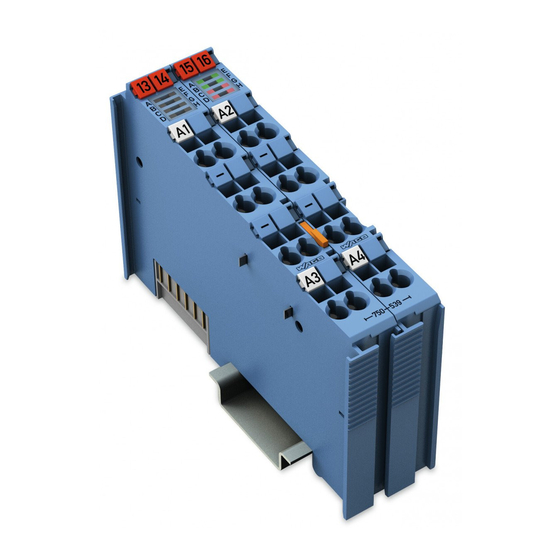
4DO 24V DC VALVE Ex i 4-Channel Digital Output Module DC 24 V, Valve Ex i For WAGO-I/O-SYSTEM 750
Brand:
WAGO
| Category:
Control Unit
| Size: 2.09 MB
Table of Contents
Table of Contents
3
1 Notes about this Documentation
5
Validity of this Documentation
5
Revision History
5
Copyright
5
Symbols
6
Number Notation
8
Font Conventions
8
Table 1: Number Notation
8
Table 2: Font Conventions
8
2 Important Notes
9
Legal Bases
9
Subject to Changes
9
Personnel Qualifications
9
Use of the WAGO-I/O-SYSTEM 750 in Compliance with Underlying Provisions
9
Technical Condition of Specified Devices
10
Safety Advice (Precautions)
11
3 Device Description
13
View
14
Figure 1: View
14
Table 3: Legend for Figure "View
14
Connectors
15
Data Contacts/Internal Bus
15
Figure 2: Data Contacts
15
Power Jumper Contacts/Field Supply
16
Figure 3: Power Jumper Contacts
16
Table 4: Legend for Figure "Power Jumper Contacts
16
CAGE CLAMP ® Connectors
17
Figure 4: CAGE CLAMP ® Connectors
17
Table 5: Legend for Figure "CAGE CLAMP ® Connectors
17
Display Elements
18
Figure 5: Display Elements
18
Table 6: Legend for Figure "Display Elements
18
Operating Elements
19
Schematic Diagram
19
Figure 6: Schematic Diagram
19
Technical Data
20
Device Data
20
Supply
20
Communication
20
Table 7: Technical Data - Device
20
Table 8: Technical Data - Supply
20
Table 9: Technical Data - Communication
20
Outputs
21
Figure 7: Output Characteristics
21
Table 10: Technical Data - Outputs
21
Explosion Protection
22
Table 11: Technical Data - Explosion Protection
22
Connection Type
23
Climatic Environmental Conditions
23
Table 12: Technical Data - Field Wiring
23
Table 13: Technical Data - Power Jumper Contacts
23
Table 14: Technical Data - Data Contacts
23
Table 15: Technical Data - Climatic Environmental Conditions
23
Approvals
24
Standards and Guidelines
25
4 Process Image
26
Table 16: Output Bits
26
Table 17: Input Bits
26
Table 18: Evaluation Matrix
26
5 Mounting
27
Mounting Sequence
27
Inserting and Removing Devices
28
Inserting the I/O Module
28
Figure 8: Insert I/O Module (Example)
28
Figure 9: Snap the I/O Module into Place (Example)
28
Removing the I/O Module
29
Figure 10: Removing the I/O Module (Example)
29
6 Connect Devices
30
Connecting a Conductor to the CAGE CLAMP
30
Figure 11: Connecting a Conductor to a CAGE CLAMP
30
Power Supply Concept
31
Figure 12: Supply Principle Ex I
32
Figure 13: Overvoltage Categories
32
Table 19: Legend for Figure "Overvoltage Categories
32
Power Supply Concept in Marine Applications
33
Figure 14: Power Supply Concept, Category EMC1 (Marine Applications)
33
Table 20: Legend for Figure "Power Supply Concept, Category EMC1 (Marine Applications)
33
Figure 15: Power Supply Concept, Category EMC2 (Marine Applications)
34
Table 21: Legend for Figure "Power Supply Concept, Category EMC2 (Marine Applications)
34
Tested Valves
35
Table 22: Tested Valves
35
Table 23: Valve Test Values (Date:10.2016)
35
Connection Example
36
Figure 16: Connection Example
36
7 Use in Hazardous Environments
37
Marking Configuration Examples
38
Marking for Europe According to ATEX and IEC-Ex
38
Figure 17: Side Marking Example for Approved I/O Modules According to ATEX and Iecex
38
Figure 18: Text Detail - Marking Example for Approved I/O Modules According to ATEX and Iecex
38
Table 24: Description of Marking Example for Approved I/O Modules According to ATEX and Iecex
39
Figure 19: Side Marking Example for Approved Ex I I/O Modules According to ATEX and Iecex
40
Figure 20: Text Detail - Marking Example for Approved Ex I I/O Modules According to ATEX and Iecex
40
Table 25: Description of Marking Example for Approved Ex I I/O Modules According to ATEX and Iecex
42
Marking for America According to NEC 500
43
Figure 21: Side Marking Example for I/O Modules
43
Figure 22: Text Detail - Marking Example for Approved I/O Modules
43
Table 26: Description of Marking Example for Approved I/O Modules
43
Installation Regulations
44
Special Conditions for Safe Use (TÜV 14 ATEX 148929 X)
45
Special Conditions for Safe Use (ATEX Certificate TÜV 12 ATEX 106032 X)
46
Special Conditions for Safe Use (IEC-Ex Certificate TUN 14.0035X)
47
Special Conditions for Safe Use (IEC-Ex Certificate Iecex TUN 12.0039 X)
48
Special Conditions for Safe Use According to ANSI/ISA 12.12.01
49
8 Appendix
50
Rated Surge Voltage
50
Table 27: Rated Surge Voltage *)
50
List of Figures
51
List of Tables
52
Advertisement
Advertisement
Related Products
WAGO 750-535
WAGO 750-535/040-000
WAGO 750-537/040-000
WAGO 750-536
WAGO 750-532
WAGO 750-538
WAGO WAGO-I/O-SYSTEM 750-506
WAGO 750-511
WAGO 750-523
WAGO 750-509
WAGO Categories
I/O Systems
Control Unit
Power Supply
Switch
Controller
More WAGO Manuals
Login
Sign In
OR
Sign in with Facebook
Sign in with Google
Upload manual
Upload from disk
Upload from URL