Sign In
Upload
Manuals
Brands
Wacker Neuson Manuals
Front End Loaders
WL 30
Wacker Neuson WL 30 Manuals
Manuals and User Guides for Wacker Neuson WL 30. We have
1
Wacker Neuson WL 30 manual available for free PDF download: Operator's Manual
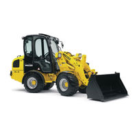
Wacker Neuson WL 30 Operator's Manual (246 pages)
Wheel Loader
Brand:
Wacker Neuson
| Category:
Front End Loaders
| Size: 4.29 MB
Table of Contents
Table of Contents
4
Preface
9
1 Basic Information
10
Notes about this Operator's Manual
11
Explanation of the Symbols Used in this Operator's Manual
12
Warranty and Liability
14
Fig. 1 Document Pocket
14
Intended Use
15
2 Basic Safety Instructions
18
Organizational Measures
19
Selection and Qualification of Personnel / Basic Duties
21
Safety Instructions for Certain Operating Phases
22
Safety Instructions for Normal Operation
22
Safety Instructions for Other Operating Modes
24
Safety Instructions for Particular Hazards
27
Forklift Attachment
27
Fig. 2 Transport of Large Bales or Packaged Goods
27
Working Near Overhead Power Lines
28
Electrical Power
29
Flying Sparks / Fire Danger
29
Gas, Dust, Steam, Smoke
30
Hydraulics, Pneumatics
30
Tip-Overs
31
Noise
31
Oils, Grease and Other Chemical Substances
31
Transporting and Towing / Restarting
32
Final Decommissioning / Dismantling
32
Safety Labels Used
33
Fig. 3 Location of the Safety Labels
33
Safety Devices
38
Fire Extinguisher
38
Rotating Beacon
38
Fig. 4 Fire Extinguisher
38
Fig. 5 Attaching the Rotating Beacon
38
Seat Belt
39
Backup Alarm for Reverse Drive
39
Fig. 6 Seat Belt
39
Emergency Exit
40
Fig. 7 Emergency Exit
40
Battery Disconnect Switch
41
Fig. 8 Battery Disconnect Switch
41
Loader Lift Arm Locking System
42
Fig. 9 Lever for the Locking Mechanism of the Loader Lift Arm
42
3 Technical Data
43
Technical Description
43
Loader Data
45
Product Identification Number Plates
47
Fig. 10 Vehicle ID
47
Dimensions
48
Fig. 11 Dimensions
48
4 Description of the Indicator, Warning and Control Elements
50
Operating Elements and Instruments
50
Fig. 12 Operating Elements
50
Control and Warning Indicator Lights
52
Fig. 13 Control and Warning Lights
52
Switches / Rocker Switches
56
Fig. 14 Switches / Rocker Switches (1)
56
Fig. 15 Switches / Rocker Switches (2)
58
Indicator Devices
60
Fig. 16 Indicator Devices
60
5 Operating and Operation
62
Before Starting up
62
Fueling
62
Fig. 17 Fuel Filler Neck
63
Operation
64
Doors and Windows
66
Fig. 18 Cab Door Locking
66
Fig. 19 Releasing Locked Cab Doors
66
Adjusting the Steering Column
67
Fig. 20 Adjusting the Steering Column
67
Adjusting the Operator's Seat
68
Fig. 21 Adjusting the Operator's Seat
68
Seat Belt
69
Fig. 22 Buckling the Seat Belt
70
Fig. 23 Adjusting the Seat Belt
71
Starting up
72
Lighting System and Forward Warning Device
72
Fig. 24 Lighting / Forward Warning Device
73
Wipers and Windshield Washer System
74
Fig. 25 Switches for Windshield Wipers
74
Fig. 26 Location of the Windshield Washer Container
75
Headlights and Rotating Beacon
76
Fig. 27 Headlight and Rotating Beacon Switches
76
Ventilation and Heating of the Cab
78
Fig. 28 Heating Controller
78
Before Starting the Engine
79
Fig. 29 Ventilation Outlets
79
Starting the Engine
80
Fig. 30 Starting Switch
80
Propulsion Operation
82
Preparation for Travel in Public Traffic
82
Travel Speed
83
Fig. 31 Changing Direction
85
Stopping and Parking
87
Work Operation
88
Operating Lever for Loader Lift Arms
90
Fig. 32 Operating Lever for Loader Lift Arms
91
Activating the Optional Hydraulics
92
Fig. 33 Operating Lever for the Optional Hydraulics
93
Fig. 34 Hydraulic Connections
93
Fig. 35 Button for Optional Hydraulics
94
Fig. 36 Depressurized Return Line
95
Loader Lift Arms Locking System
96
Fig. 37 Lever for the Locking Mechanism of the Loader Lift Arms
96
Differential Lock
97
Fig. 38 Switch for Differential Lock
97
Changing Attachments
98
Fig. 39 Coupling and Uncoupling Tools
101
Bucket
103
Fig. 40 Control Lever Movements
104
Fig. 41 Level Indicator
105
Fig. 42 Loading Work 1
106
Fig. 43 Loading Work 2
107
Fig. 44 Loading Work 3
107
Fig. 45 Excavation Work 4
108
Fig. 46 Excavation Work 5
108
Tip-Overs
109
Precaution Measures for Various Temperature Conditions
110
Optional Equipment
112
Fig. 47 Switch for Loader Lift Arm Vibration Damping
113
Fig. 48 Optional Hydraulics Control Lever
114
Fig. 49 Electrical Connector on the Loader Lift Arms
115
Fig. 50 Switch for the Electrical Connector on the Loader Lift Arms
115
6 Towing and Transporting
116
Towing
116
Fig. 51 Towing Equipment
117
Fig. 52 Disconnecting the Drive
118
Transporting
120
Fig. 53 Articulation Frame Lock
121
Fig. 54 Attachment Point Label
123
Fig. 55 Attachment Points
123
Fig. 56 Tie down Point Label
125
Fig. 57 Tie down Points
125
Fig. 58 Tying down the Loader
126
7 Lowering Loader Arms
127
8 Relieving Residual Pressure in the Hydraulic System
128
Fig. 59 Reducing Residual Pressure
129
Fig. 60 Load Holding Control Valve
130
9 Securing the Loader
131
10 Servicing and Inspection
132
Basic Safety Instructions for Servicing and Inspection
132
Servicing and Inspection Intervals
140
Lubrication Schedule
152
Fig. 61 Points of Lubrication
152
Cleaning the Loader
154
General Safety Check
156
Specifications and Filling Quantities
157
Maintenance and Inspection Work
158
Preparation for Maintenance and Inspection Work
158
Fig. 62 Handle for the Engine Enclosure
159
Fig. 63 Cab Tilt Lever
161
Fig. 64 Position of the Cab Mounting Bolts
162
Fig. 65 Cab Safety Support
163
Servicing the Engine
164
Fig. 66 Checking the Engine Oil / Filling the Oil
165
Fig. 67 Engine Oil Drain Opening
167
Fig. 68 Location of the Engine Oil Filter
169
Fig. 69 Engine Oil Filter
169
Servicing the Fuel System
170
Fig. 70 Water Separator
171
Fig. 71 Fuel Pre-Filter, Main Fuel Filter
172
Fig. 72 Changing the Main Fuel Filter
173
Fig. 73 Venting the Fuel System
174
Servicing the Air Filter System
175
Fig. 74 Location of the Air Filter
176
Fig. 75 Air Filter Elements
176
Servicing the Cooling System
178
Fig. 76 Radiator
178
Fig. 77 Engine Temperature Sensor
179
Fig. 78 Hydraulic Oil Temperature Sensor
179
Fig. 79 Radiator Opening
181
Fig. 80 Checking the Antifreeze MIX
181
Fig. 81 Cleaning the Cooling System
183
Servicing the Hydraulic System
184
Fig. 82 Hydraulic Fluid Cooler
185
Fig. 83 Ventilation Filter
187
Fig. 84 Hydraulic Fluid Dip Stick
187
Fig. 85 Hydraulic Fluid Drain Plugs
189
Fig. 86 Return Filter
191
Fig. 87 Filter Insert
191
Servicing the Axles
193
Fig. 88 Differential
193
Fig. 89 Transfer Case
194
Fig. 90 Wheel Reduction
194
Servicing the Cab Vent Filter
197
Fig. 91 Cab Vent Filter
197
Servicing the Brakes
198
Fig. 92 Brake Fluid Container
199
10.7.10 Servicing the Tires and Wheels
200
10.7.11 Servicing the Electrical System
204
Jump-Starting / Emergency Starting
212
Loader Storage
215
11 Troubleshooting and Emergency Maintenance
218
12 Safety Instructions for Repairs
222
General Safety Regulations for Repairs
222
Engine
225
Welding Work
225
Hydraulic System
227
Brakes
227
13 Final Shutdown of the Loader / Decommissioning
228
14 Appendix
230
Ordering Replacement Parts
230
Inspection Verification
232
Index
236
List of Figures
240
Advertisement
Advertisement
Related Products
Wacker Neuson WL 50
Wacker Neuson WL 750
Wacker Neuson WL 850
Wacker Neuson WM 720
Wacker Neuson WP1550A US
Wacker Neuson WP1550Aw CN
Wacker Neuson WP1540Aw US
Wacker Neuson WP1540A US
Wacker Neuson WM 80
Wacker Neuson WP1550Aw US
Wacker Neuson Categories
Power Tool
Portable Generator
Construction Equipment
Water Pump
Excavators
More Wacker Neuson Manuals
Login
Sign In
OR
Sign in with Facebook
Sign in with Google
Upload manual
Upload from disk
Upload from URL