Sign In
Upload
Manuals
Brands
WÄRTSILÄ Manuals
Engine
WARTSILA32
WÄRTSILÄ WARTSILA32 Manuals
Manuals and User Guides for WÄRTSILÄ WARTSILA32. We have
1
WÄRTSILÄ WARTSILA32 manual available for free PDF download: Product Manual
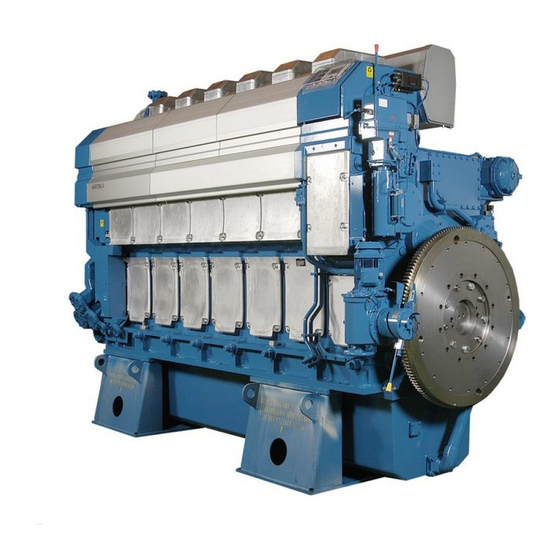
WÄRTSILÄ WARTSILA32 Product Manual (255 pages)
4-stroke, non-reversible, turbocharged and intercooled diesel engine with direct fuel injection
Brand:
WÄRTSILÄ
| Category:
Engine
| Size: 11.31 MB
Table of Contents
Introduction
3
Table of Contents
4
1 Main Data and Outputs
7
Maximum Continuous Output
7
Rating Table for Wärtsilä 32
7
Reference Conditions
9
Operation in Inclined Position
9
Arctic Package Description
9
Dimensions and Weights
10
Main Engines
10
In-Line Engines with 500Kw/Cyl (DAAE030112A)
10
Generating Sets
14
In-Line Engines with 500Kw/Cyl (DAAE030093)
14
2 Operating Ranges
19
Engine Operating Modes
19
Engine Operating Range
19
Operating Field for CP Propeller, 500 Kw/Cyl, 750 Rpm
20
Operating Field for CP Propeller, 580 Kw/Cyl, 750 Rpm
20
Fixed Pitch Propellers
21
Dredgers
21
Operating Field for FP Propeller, 500 Kw/Cyl), 750 Rpm
21
Loading Capacity
22
Mechanical Propulsion
22
Maximum Recommended Load Increase Rates for Variable Speed Engines
22
Diesel Electric Propulsion and Auxiliary Engines
23
Maximum Instant Load Steps (500 Kw/Cyl)
23
Maximum Instant Load Steps (580 Kw/Cyl)
24
Start-Up Time
24
Operation at Low Load and Idling
24
Low Air Temperature
24
3 Technical Data
25
Wärtsilä 6L32, 720 Rpm
25
Wärtsilä 6L32, 750 Rpm
28
Wärtsilä 8L32, 720 Rpm
32
Wärtsilä 8L32, 750 Rpm
35
Wärtsilä 9L32, 720 Rpm
38
Wärtsilä 9L32, 750 Rpm
41
Wärtsilä 12V32, 720 Rpm
45
Wärtsilä 12V32, 750 Rpm
48
Wärtsilä 16V32, 720 Rpm
51
Wärtsilä 16V32, 750 Rpm
54
4 Description of the Engine
57
Definitions
57
Main Components and Systems
57
Engine Block
57
Connecting Rod
58
Cylinder Liner
58
Piston Rings
58
Cylinder Head
58
Camshaft and Valve Mechanism
59
Camshaft Drive
59
Turbocharging and Charge Air Cooling
59
Fuel Injection Equipment
59
Lubricating Oil System
60
9 Cooling Water System
60
Automation System
60
Exhaust Pipes
60
Cross Section of the Engine
62
Cross Section of the In-Line Engine
62
Cross Section of the V-Engine
63
Engine Storage
64
Overhaul Intervals and Expected Life Times
64
Time between Overhaul and Expected Life Time
64
5 Piping Design, Treatment and Installation
65
Pipe Dimensions
65
Trace Heating
66
Pressure Class
66
Recommended Maximum Velocities on Pump Delivery Side for Guidance
66
Pipe Class
67
Classes of Piping Systems as Per DNV Rules
67
Insulation
68
Local Gauges
68
Cleaning Procedures
68
Cleanliness During Pipe Installation
68
Pickling
69
Flexible Pipe Connections
69
Clamping of Pipes
70
Flexible Hoses
70
Flange Supports of Flexible Pipe Connections (4V60L0796)
71
Pipe Clamp for Fixed Support (4V61H0842)
71
6 Fuel Oil System
73
Acceptable Fuel Characteristics
73
Marine Diesel Fuel (MDF)
73
MDF Specifications
73
Heavy Fuel Oil (HFO)
75
HFO Specifications
75
Liquid Bio Fuels
77
Straight Liquid Bio Fuel Specification
77
Biodiesel Specification Based on en 14214:2012 Standard
78
Crude Oil
79
Crude Oil Specification
79
Internal Fuel Oil System
80
Internal Fuel Oil System, In-Line Engines (DAAE005307D)
80
Sensors and Indicators
80
Internal Fuel Oil System, V-Engines (DAAE005308E)
81
Leak Fuel System
82
External Fuel Oil System
82
Fuel Heating Requirements HFO
82
Fuel Tanks
83
Settling Tank, HFO (1T02) and MDF (1T10)
84
Day Tank, HFO (1T03) and MDF (1T06)
84
Leak Fuel Tank, Clean Fuel (1T04)
84
Leak Fuel Tank, Dirty Fuel (1T07)
84
Separator Mode of Operation
85
Separation Efficiency
85
Separator Unit (1N02/1N05)
85
Separator Feed Pumps (1P02)
86
Separator Pre-Heater (1E01)
86
Fuel Transfer and Separating System (V76F6626F)
86
Separator (1S01/1S02)
87
MDF Separator in HFO Installations (1S02)
87
Sludge Tank (1T05)
87
Fuel Feed System - MDF Installations
88
Typical Example of Fuel Oil System (MDF) Without Engine Driven Pump
89
Circulation Pump, MDF (1P03)
90
Stand-By Pump, MDF (1P08)
90
Flow Meter, MDF (1I03)
90
Fine Filter, MDF (1F05)
90
Pressure Control Valve, MDF (1V02)
91
MDF Cooler (1E04)
91
Return Fuel Tank (1T13)
92
Black out Start
92
Fuel Feed System - HFO Installations
93
Example of Fuel Oil System (HFO) Single Engine Installation
93
Starting and Stopping
97
Changeover from HFO to MDF
97
Number of Engines in the same System
97
Feeder/Booster Unit (1N01)
97
Fuel Feed Pump, Booster Unit (1P04)
98
Feeder/Booster Unit, Example (DAAE006659)
98
Pressure Control Valve, Booster Unit (1V03)
99
Automatic Filter, Booster Unit (1F08)
99
Flow Meter, Booster Unit (1I01)
99
De-Aeration Tank, Booster Unit (1T08)
100
Circulation Pump, Booster Unit (1P06)
100
Heater, Booster Unit (1E02)
100
Pump and Filter Unit (1N03)
101
Viscosimeter, Booster Unit (1I02)
101
Circulation Pump (1P12)
101
Safety Filter (1F03)
101
Overflow Valve, HFO (1V05)
102
Flushing
102
Lubricating Oil Requirements
103
Engine Lubricating Oil
103
Oil in Speed Governor or Actuator
103
Oil in Turning Device
103
7 Lubricating Oil System
103
Lubricating Oil System in Arctic Conditions
104
Internal Lubricating Oil System
105
External Lubricating Oil System
113
Lubricating Oil System, Main Engines (V76E4562D)
113
Lubricating Oil System, Auxiliary Engines (3V76E4563C)
114
Separation System
115
Separator Feed Pump (2P03)
115
Separator Preheater (2E02)
115
Separator Unit (2N01)
115
Renovated Oil Tank (2T05)
116
Renovating Oil Tank (2T04)
116
System Oil Tank (2T01)
116
Example of System Oil Tank Arrangement (Daae007020E)
117
New Oil Tank (2T03)
117
Suction Strainers (2F01, 2F04, 2F06)
117
Condensate Trap
118
Crankcase Ventilation System
118
Lubricating Oil Pump, Stand-By (2P04)
118
External Oil System
119
Flushing Instructions
119
Piping and Equipment Built on the Engine
119
Type of Flushing Oil
119
Lubricating Oil Sample
120
8 Compressed Air System
121
Instrument Air Quality
121
Internal Compressed Air System
121
Internal Starting Air System 500 Kw/Cyl, In-Line Engines (DAAE005311F)
122
Internal Starting Air System 580 Kw/Cyl, In-Line Engines (DAAF057029C)
123
External Compressed Air System
126
Starting Air Compressor Unit (3N02)
126
Air Vessels (3T01 & 3T05)
127
Oil and Water Separator (3S01)
127
Starting Air Vessel (3T01)
127
Air Assist Vessel (3T05)
128
Air Filter, Starting Air Inlet (3F02)
128
Air Assist (for 560 & 580 Kw/Cyl)
129
Air Filter, Air Assist Inlet (3F03)
129
Cooling Water System
131
Corrosion Inhibitors
131
Glycol
131
Water Quality
131
Internal Cooling Water System
132
Internal Cooling Water System, Two Stage Air Cooler, In-Line Engines
132
Internal Cooling Water System, V-Engines (DAAE005314D)
133
Engine Driven Circulating Pumps
134
Example Diagram for Single Main Engine (MDF) (3V76C5775C)
135
External Cooling Water System
135
Cooling Water System for Arctic Conditions
142
Dimensioning the HT Water Heaters
142
HT-Circuit Heating Operational Field
142
The Arctic Sea Water Cooling System
142
Example Flow Diagram of Arctic Sea Water System
143
Sea Water Pump (4P11)
143
Stand-By Circulation Pumps (4P03, 4P05)
143
Temperature Control Valve, HT-System (4V01)
143
Coolers for Other Equipment and MDF Coolers
144
Fresh Water Central Cooler (4E08)
144
Temperature Control Valve for Central Cooler (4V08)
144
Temperature Control Valve for Heat Recovery (4V02)
144
Air Venting
146
Expansion Tank (4T05)
146
Waste Heat Recovery
146
Drain Tank (4T04)
147
Heater (4E05)
147
Minimum Diameter of Balance Pipe
147
Preheating
147
Circulation Pump for Preheater (4P04)
148
Preheating Unit (4N01)
148
Preheating Unit, Electric (3V60L0562C).
149
Thermometers and Pressure Gauges
149
Throttles
149
10 Combustion Air System
151
Engine Room Ventilation
151
Engine Room Ventilation, Turbocharger with Air Filter (DAAE092651)
152
Combustion Air System Design
153
Engine Room Ventilation, Air Duct Connected to the Turbocharger
153
Charge Air Shut-Off Valve, "Rigsaver" (Optional)
154
Combustion Air System Design in Arctic Conditions
154
Condensation in Charge Air Coolers
154
Ensuring Correct Compressor Performance
155
Example Scheme of Air and Exhaust Waste Gate Arrangement
156
Suction Air Piping
156
11 Exhaust Gas System
157
Internal Exhaust Gas System
157
Internal System, In-Line Engines, 500 Kw/Cyl (DAAE005315F)
157
Internal System, In-Line Engines, 580 Kw/Cyl (DAAF057034A)
158
Internal System, V-Engines, 500 Kw/Cyl (DAAE005316F)
159
Internal System, V-Engines, 580 Kw/Cyl (DAAF057036A)
160
Exhaust Gas Outlet
161
Exhaust Pipe Connections
161
Exhaust Pipe, Diameters and Support
162
Exhaust Pipe, Diameters and Support (DAAE057873D, -74D)
162
External Exhaust Gas System
163
Piping
163
Back Pressure
164
Supporting
164
Exhaust Gas Bellows (5H01, 5H03)
165
Exhaust Gas Boiler
165
SCR-Unit (11N14)
165
Exhaust Gas Silencers
166
Exhaust Noise
166
Exhaust Noise, Source Power Corrections
166
Compact Silencer System (5N02)
167
Silencer System Comparison
167
Conventional Exhaust Gas Silencer (5R02)
168
Exhaust Gas Silencer (3V49E0142C)
168
Typical Dimensions of Exhaust Gas Silencers
168
12 Turbocharger Cleaning
169
Turbine Cleaning System
169
Turbocharger Cleaning System (4V76A2937A)
169
Compressor Cleaning System
170
13 Exhaust Emissions
171
Diesel Engine Exhaust Components
171
Nitrogen Oxides
171
Sulphur Oxides
171
International Maritime Organization (IMO)
172
ISO 8178 Test Cycles
172
Marine Exhaust Emissions Legislation
172
MARPOL Annex VI - Air Pollution
172
Engine Family/Group
173
IMO Nox Emission Standards
173
Technical File
173
Fuel Sulphur Caps
175
Methods to Reduce Exhaust Emissions
176
Other Legislations
176
Architecture of UNIC C2
177
Unic C2
177
14 Automation System
177
Local Control Panel and Local Display Unit
178
Operational Functions Available at the LCP
178
Engine Safety System
179
Power Unit
179
Cabling and System Overview
180
Ethernet Communication Unit
180
Typical Amount of Cables
180
UNIC C2 Overview
180
Signal Overview (Main Engine)
181
Functions
182
Signal Overview (Generating Set)
182
Start
182
Startblockings
182
Main Engines (Mechanical Propulsion)
183
Speed Control
183
Stop and Shutdown
183
Alarm and Monitoring Signals
184
Electrical Consumers
184
Engine Turning Device (9N15)
184
Motor Starters and Operation of Electrically Driven Pumps
184
Circulating Pump for Preheater (4P04)
185
Stand-By Pump, HT Cooling Water (if Installed) (4P03)
185
Stand-By Pump, LT Cooling Water (if Installed) (4P05)
185
Stand-By Pump, Lubricating Oil (if Installed) (2P04)
185
15 Foundation
187
Mounting of Main Engines
187
Rigid Mounting
187
Steel Structure Design
187
Resin Chocks
188
Steel Chocks
188
Steel Chocks with Adjustable Height
188
Main Engine Seating and Fastening, In-Line Engines, Steel Chocks
189
Number of Pieces Per Engine
190
Main Engine Seating and Fastening, In-Line Engines, Resin Chocks
191
Main Engine Seating and Fastening, V-Engines, Steel Chocks
193
Principle of Resilient Mounting, W6L32 and W8L32 (DAAE048811)
197
Resilient Mounting
197
Principle of Resilient Mounting, W12V32 and W16V32 (DAAE041111A)
198
Principle of Resilient Mounting, W9L32 (2V69A0247A)
198
Principle of Resilient Mounting, W18V32 (2V69A0248A)
199
Distance between Fixing Bolts on Generator (4V92F0143B)
200
Generator Feet Design
200
Mounting of Generating Sets
200
Recommended Design of the Generating Set Seating
202
Rubber Mounts
202
Flexible Pipe Connections
203
Rubber Mount, In-Line Engines (Daae004230C)
203
Rubber Mount, V-Engines (Daae018766B)
203
16 Vibration and Noise
205
Coordinate System
205
External Forces and Couples
205
Torque Variation at 0% Load
206
Torque Variation at 100% Load for 550 & 580 Kw/Cyl
206
Torque Variations
206
Air Borne Noise
207
Mass Moments of Inertia
207
Typical Sound Power Level for Engine Noise, W L32
207
Exhaust Noise
208
17 Power Transmission
211
Connection Engine-Generator (3V64L0058C)
211
Connection to Generator
211
Flexible Coupling
211
Clutch
212
Directives for Generator End Design (4V64F0003A)
212
Shaft Locking Device
212
Power Take off at Free End (4V62L1260C)
213
Power-Take-Off from the Free End
213
Shaft Locking Device and Brake Disc with Calipers
213
Input Data for Torsional Vibration Calculations
214
Main Generator or Shaft Generator
214
Propeller and Shafting
214
Reduction Gear
214
Flexible Coupling/Clutch
215
Operational Data
215
Turning Gear
215
18 Engine Room Layout
217
Crankshaft Distances
217
In-Line Engines, Turbocharger in Free End (DAAE041961)
217
V Engines, Turbocharger in Free End (Daae042488A)
218
In-Line Engines, Turbocharger in Driving End (Daae030105A)
219
V Engines, Turbocharger in Driving End (DAAE053931)
220
In-Line Engines, Turbocharger in Free End (DAAE041218)
221
V-Engines, Turbocharger in Free End (DAAE040884B)
222
Example of Father-And-Son Arrangement, 9L32 + 12V32, TC in Free End
223
Father-And-Son Arrangement
223
Distance from Adjacent Intermediate/Propeller Shaft
225
Main Engine Arrangement, In-Line Engines (DAAE059183)
226
Main Engine Arrangement, V-Engines (DAAE059181A)
226
Main Engine Arrangement, In-Line Engines (DAAE059178)
227
Main Engine Arrangement, V-Engines (DAAE059176)
227
Engine Room Height and Lifting Equipment
228
Maintenance Platforms
228
Space Requirements for Maintenance
228
Working Space Around the Engine
228
Service Space Requirement for the In-Line Engine
229
Service Space Requirement (580 Kw/Cyl), Turbocharger in Free End
230
Service Space Requirement for the V-Engine
231
Service Space Requirement, Turbocharger in Driving End
231
Service Space Requirement (580 Kw/Cyl), Turbocharger in Driving End
233
Service Space Requirement (500 Kw/Cyl), Genset
235
Service Space Requirement (580 Kw/Cyl), Genset
236
Service Space Requirement (580 Kw/Cyl), Genset (DAAF032607B)
236
19 Transport Dimensions and Weights
239
Lifting of Main Engines
239
Lifting of Main Engines, V-Engines (2V83D0253F)
240
Lifting of Generating Sets
241
Lifting of Generating Sets (3V83D0251C, -252B)
241
Engine Components
242
Turbocharger and Cooler Inserts (2V92L1099C)
242
Major Spare Parts (500 Kw/Cyl), (1V92L1098B)
244
Weights for 1V92L1098B
244
Major Spare Parts (580 Kw/Cyl), (DAAF049715A)
245
Weights for DAAF049715A
245
20 Product Guide Attachments
247
21 Annex
249
Prefix
249
The most Common Prefix Multipliers
249
Unit Conversion Tables
249
Collection of Drawing Symbols Used in Drawings
250
Advertisement
Advertisement
Related Products
WÄRTSILÄ WARTSILA 34DF
WÄRTSILÄ WARTSILA 20
WÄRTSILÄ W-X62
WÄRTSILÄ 12V34DF
WÄRTSILÄ 12V46F
WÄRTSILÄ 14V46F
WÄRTSILÄ 16V34DF
WÄRTSILÄ 16V46F
WÄRTSILÄ 22606
WÄRTSILÄ 22607
WÄRTSILÄ Categories
Engine
UPS
Marine Equipment
Accessories
More WÄRTSILÄ Manuals
Login
Sign In
OR
Sign in with Facebook
Sign in with Google
Upload manual
Upload from disk
Upload from URL