Sign In
Upload
Manuals
Brands
Volkswagen Manuals
Automobile
Bora 2004
Volkswagen Bora 2004 Compact Sedan Manuals
Manuals and User Guides for Volkswagen Bora 2004 Compact Sedan. We have
1
Volkswagen Bora 2004 Compact Sedan manual available for free PDF download: Service Manual
Volkswagen Bora 2004 Service Manual (340 pages)
Brand:
Volkswagen
| Category:
Automobile
| Size: 1.7 MB
Table of Contents
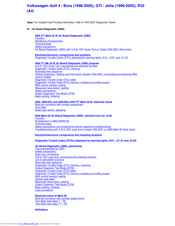
ABS ITT Mark 20 IE on Boarddiagnostic (OBD)
2
Function
2
V.A.G 1551 Scan Tool or Tester VAS 5051
4
Identifying Characteristics
5
Distinguishing Features
5
Distinguishing Features of ABS, ABS/EDL and ABS/EDL/ASR ITT Mark 20 IE Hydraulic Unit
5
Technical Data
6
Control Module Identification
6
Diagnostic Trouble Code (DTC) Memory
6
Safety Precautions
7
On Board Diagnostic (OBD) with V.A.G 1551 Scan Tool or Tester VAS 5051 (Flow Chart)
8
Electrical/Electro Components and Locations
10
ABS Hydraulic Unit N55-
10
ABS Control Module (W/Edl)-J104-
11
ABS/EDL and ABS/EDL/ASR Hydraulic Unit-N55-
12
ABS/EDL and ABS/EDL/ASR Control Module-J104-
13
Brake Lightswitch-F-
14
Data Link Connector (DLC)
14
Longitudinal Acceleration Sensor-G251
14
ABS Warning Light-K47-
15
Warning Light for Brake System-K118-
15
ESP Control Lamp-K155-
15
Right/Left Front ABS Wheel Speedsensor -G45-/-G47-
16
Wheel Hub with Impulse Rotor for Right/Left Front Speed Sensors
16
Right/Left Rear ABS Wheel Speed Sensor-G44-/-G46-
18
Wheel Hub with Impulse Rotor for Right/Left Rear Speed Sensors
18
Diagnostic Trouble Codes (DTC) Displayed by Warning Lights -K14-, -K47- and -K118-
20
Warning Lights
20
ABS Warning Light -K47-
21
ABS Warning Lights -K47- and -K118-
22
Electrical Wiring Diagrams, Troubleshooting & Component Locations Binder
22
Parking Brake Indicator Light -K14-
23
Vehicles with ABS/EDL
23
Malfunction: Vehicle Has no EDL Function
23
ABS ITT Mk 20 IE on Board Diagnostic (OBD) Program
24
Special Tools and Equipment
24
Test Requirements
25
V.A.G 1551 Scan Tool, Connecting and Selecting Function
26
Indicated on Display
26
V.A.G-On Board Diagnostic
26
Rapid Data Transfer
27
Workshop Code
28
List of Selectable Functions
30
Diagnostic Trouble Code (DTC), Memory
31
Work Sequence if a DTC Has Been Detected
32
Automatic Test Sequence
33
V.A.G - on Board Diagnostic
33
Vehicle Diagnosis, Testing and Information System VAS 5051, Connecting and Selecting ABS Control Module
34
Select Operating Mode
36
Select Vehicle System
36
Select Diagnostic Function
37
Diagnostic Trouble Code (DTC) Table
38
Diagnostic Trouble Code (DTC) Memory, Erasing and Ending Output
59
Erasing DTC Memory
59
Ending Output
60
ABS Control Module, Coding
61
Coding Control Module
62
Coding Table
63
Measured Value Block, Reading
64
Observe Following if Test and Measuring Instruments Are Required During a Test Drive
65
Read Measured Value Block
66
List of Selectable Display Group Numbers
67
Test Sequence and Test Tables with Measured Values
69
Checking Speed Sensor Allocation
69
Display Group Number 001
69
For Display Group Number 001 Remember
70
Checking Speed Sensor
71
Display Group Number 002
71
For Display Group Number 002 Remember
72
Checking Brake Light Switch for ABS and ABS/EDL Function
73
Display Group Number 003
73
Checking Data Bus Wiring
75
Display Group Number 125
75
Output Diagnostic Test Mode (DTM)
77
Indicated on V.A.G 1551 Display During Output Diagnostic Test Mode (DTM)
78
Output Diagnostic Test Mode
80
Indicated on Display (Vehicles with EDL)
92
Function Is Unknown or Cannot be Carried out at the Moment
93
Basic Setting, Initiating
94
Display Group Number 01: Bleeding Hydraulic Unit
95
System in Basic Setting
96
ABS, ABS/EDL and ABS/EDL/ASR ITT Mark 20 IE, Electrical Check
105
Removing Air Cleaner
107
Release ABS Control Module (W/Edl) -J104- Connector-Arrow 1- and Pull Off-Arrow 2-
108
Connect Test Box V.A.G 1598/21 -1- to Multi-Pin Connector of ABS Control Module (W/Edl) -J104- (-2-)
108
Multi-Pin Connector with Contact Assignment
109
Contact Assignment of Connectors for Voltage Supply and on Board Diagnostic(OBD) with V.A.G 1551 Scan Tool
109
Contact Assignment of Connector T25 Wiring Harness/Abs Control Module (W/Edl) -J104-
109
Wiring Connection to Component
110
Test Step Overview
112
Test Table
114
Switch to Measuring Range: Voltage Measurement (20 V =)
115
Switch to Measuring Range: Resistance Measurement (2 K)
117
Switch to Measuring Range: Voltage Measurement
121
Switch to Measuring Range: Resistance Measurement (200)
123
Switch to Measuring Range: Resistance Measurement 200
125
Functional Check: ABS Warning Light -K47-
126
Functional Check: Warning Light for Brake System -K118-
127
Functional Check: ABS Hydraulic Pump -V64-
128
Switch to Measuring Range: Resistance Measurement (20020)
129
Continuation of Test Step 19
130
Switch to Measuring Range: Resistance Measurement (200/20)
131
Continuation of Test Step 20
132
Functional Check: ESP Control Lamp -K155
133
Brake Light Switch, Adjusting
134
Vehicle up to My 02.00
134
Vehicle from My 03.00
135
ABS Mark 60 on Board Diagnostic (OBD), Vehicles from My 10.00
136
The ESP Is a Further Extension of the Familiar Vehicle Safety Systems
136
During this Period a Test Sequence (Self-Check) Is Run in the Control Module for the Following Functions
138
Features of 4MOTION
139
Special Detail for Bleeding Brake Systems with ABS/EDL
139
Arrangement of ABS MARK 60
140
Safety Precautions and Fundamental Points Regarding Troubleshooting
142
Technical Information
143
Troubleshooting with V.A.G 1551 Scan Tool or Tester VAS 5051 on ABS Mark 60 (Flow Chart)
144
Electrical/Electro Components and Installing Location
146
ABS Control Module (W/Edl) -J104-
147
Vehicles with ABS/ESP Only
147
Sender for Rotation Rate -G202-
149
Vehicles with ABS/EDL/ASR/ESP Only
149
Sensor for Transverse Acceleration -G200-
150
Longitudinal Acceleration Sensor -G251-
151
ESP-Sensor Unit -G419-, Vehicles from 02.02
152
Sender 1 for Brake Booster -G201-
154
Brake Booster
155
Steering Angle Sensor -G85-
155
Brake System Vacuum Pump -V192-
156
Button for ASR/ESP -E256-
158
Warning Light for Brake System -K118-
158
ASR/ESP Control Lamp -K155-
158
Right/Left Front ABS Wheel Speed Sensor -G45-/-G47-
159
Wheel Hub with Rotor for Speed Sensors
159
Right/Left Rear Speed Sensor -G44-/-G46-
161
Diagnostic Trouble Codes (Dtcs) Displayed by Warning Lights -K47-, -K118- and -K155-
163
Warning Lights -K47- and -K118-
165
On Board Diagnostic (OBD), Performing
167
Test Prerequisites for OBD
167
Scan Tool, Connecting
169
Connecting VAS 5051
170
Selecting Operating Mode
170
Selecting Vehicle System
170
Selecting Diagnosis Function
170
V.A.G 1551 or V.A.G 1552 Scan Tool Vehicle System Tester
171
V.A.G 1551/3 or 1551/3A Adapter Cable
171
If "Control Module Does Not Answer!" Again Appears
175
V.A.G - on Board Diagnosic
177
Diagnostic Trouble Code (DTC) Memory, Checking
178
Check DTC Memory (Function
179
Output Diagnosic Test Mode (DTM)
180
Indicated on V.A.G 1551 Display During Output DTM
181
Output Diagnosic Test Mode
183
ABS Hydraulic Pump-V64 no Longer Runs
185
ABS Hydraulic Pump -V64- no Longer Runs
188
The ABS Warning Light -K47- Goes out
196
Test Sequence
241
Vehicle Data Label
242
Explanation of the PR. Numbers on Vehicle Data Label
242
Location of Optional Equipment Number (PR No.) on Vehicle Data Plate (Arrow)
242
Table for ABS, Coding
244
With Control Unit Identification Number 1C0 907 379 C/J/L for Vehicles from 10.00
244
Table for ABS/EDL/ASR, Coding
245
With Control Unit Identification Number 1C0 907 379 D/K for Vehicles from 10.00
245
Table for ABS/EDL/ASR/ESP, Coding
246
Vehicles with Front Wheel Drive
246
With Control Unit Identification Number 1C0 907 379 E/G/M for Vehicles from 10.00
246
4MOTION Vehicles
247
With Control Unit Identification Number 1C0 907 379 F/H/N
247
Overview of Selectable Display Group Numbers
250
Checking Brake Light Switch, Brake System Warning Lamp, ABS Warning Lamp and ASR/ESP Warning Lamp
257
Checking Steering Angle Sensor, Sensor for Transverse Acceleration and Sender for Rotation Rate
259
Checking Sensor for Transverse Acceleration -G200-
261
Checking Brake Pressure Sensor
263
Display Group Number 005
263
Checking Longitudinal Acceleration Sensor -G251-
265
Display Group Number 006
265
Function 04 "Initiate Basic Setting" Performs Several Functions with ABS Mark 60
272
When the ABS Control Module (W/Edl) -J104- Is Replaced, a Zero Compensation Must be Performed for the Following Components
273
VAS 5234 Brake Filler and Bleeder Unit
274
Basic Setting
275
When All 8 Cycles Have Been Performed, this Message Appears on the Display
276
Display Group Number 40: Switching off Longitudinal Acceleration Sensor -G251-
277
Display Group Number 60: Zero Compensation of Steering Angle Sensor -G85-
279
Basic Setting 60 off (4-On)
281
Function Is Unknown or Cannot Be-Performed at Moment
281
Erase DTC Memory (Function
282
Display Group Number 63: Zero Compensation of Sensor for Transverse Acceleration -G200-
283
Basic Setting 63 off (4-On)
284
End Output (Function
285
Display Group Number 66: Zero Compensation for Sender 1 for Brake Booster -G201-
286
Display Group Number 69: Zero Compensation of Longitudinal Acceleration Sensor -G251-
289
Basic Setting 69 off (4-On)
290
Display Group Number 93: Activation of ESP Driving Test
292
Basic Setting 93 on (8)
293
Login Procedure
295
Coding 2
295
Electrical Check of Mark 60
296
Connect Test Box V.A.G 1598/36 -1- to Multi-Pin Connector of ABS Control Module (W/Edl) -J104- -2-
299
Multi-Pin Connector with Contact Assignments
300
Contact Assignment of Connectors for Voltage Supply and Self-Diagnosis with the V.A.G 1551 Scan Tool
300
Contact Assignment of Connector T47 Wiring Harness/Abs Control Module (W/Edl) -J104-
300
Perform Test Step
305
Perform Test Step
306
Switch to Measuring Range: Resistance Measurement (2 K)
310
Switch to Measuring Range: Voltage Measurement (2 V)
314
Functional Check: ESP Control Lamp -K155-
318
Functional Check: Warning Lamp for ASR/ESP Button -E256-
319
Test Table (Test Steps 17-23)
321
Switch to Measuring Range: Voltage Measurement (20 V =) in Test Step 17, Resistance Measurement (200) in Test Step 17A
321
Continuation of Test Step 17
322
Switch to Measuring Range: Resistance Measurement (200/20M)
323
Continuation of Test Step 18
326
Definitions
334
Abs & Asr
334
Data Bus Low (High)
334
Speed Sensor
334
Ebd & Edl
335
On Board Diagnostic (OBD)
335
Performing on Board Diagnostic (OBD)
335
Performing Electrical Check
335
No Communication
336
Short to Ground
336
Short to Positive
337
Brake Pressure Release Solenoid -F84-
337
Magnetic Coil for Brake Pressure, in Brake Booster, -N247-
337
Ebc
337
Sender 1 for Brake Booster/Sensor -2- for Brake Pressure -G201-/-G214-
338
Program Card Version
338
Sporadic
338
Infinity
338
Forget-Malfunction Counter
339
Advertisement
Advertisement
Related Products
Volkswagen Bora 2006
Volkswagen Bora 1998
Volkswagen Bora 1999
Volkswagen Bora 2000
Volkswagen Bora 2001
Volkswagen Bora 2002
Volkswagen Bora 2003
Volkswagen Bora 2005
Volkswagen Beetle 1978
Volkswagen Beetle 1973
Volkswagen Categories
Automobile
Automobile Accessories
Adapter
Cables and connectors
Car Receiver
More Volkswagen Manuals
Login
Sign In
OR
Sign in with Facebook
Sign in with Google
Upload manual
Upload from disk
Upload from URL