Sign In
Upload
Manuals
Brands
veeder-root Manuals
Other
EMR4
veeder-root EMR4 Manuals
Manuals and User Guides for veeder-root EMR4. We have
4
veeder-root EMR4 manuals available for free PDF download: Setup And Operation Manual, Application Manual, Technical Installation Manual, Pc Setup Quick Help Manual
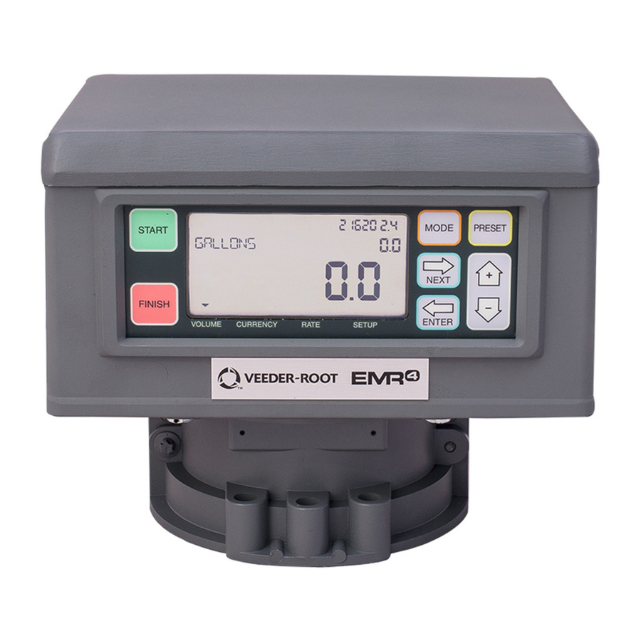
veeder-root EMR4 Setup And Operation Manual (80 pages)
Measuring and monitoring relays
Brand:
veeder-root
| Category:
Other
| Size: 2.96 MB
Table of Contents
Table of Contents
3
Introduction
7
System Features
7
System Setup
7
Setup Mode
7
C&C Mode
8
Related Manuals
8
Safety Symbols
9
Safety Warnings
9
Display Head
10
Figure 1. Display Head Features
10
Figure 2. Display Head with Optional Keypad
10
Boot-Up Test Sequence
11
Figure 3. All Segments Activated
11
Figure 4. All Zeros Activated in the Display Fields
11
Activating the Display
12
OEM Message Disabled
12
OEM Message Enabled
12
Display Value Fields
12
Register Field
12
Preset Field
12
Totalizer Field
12
Descriptor Field
12
Display Icons and Indicators
12
Display Button Functions - Standard Keypad
13
Display Button Functions - Optional Keypad
13
Data Entry
14
Navigation Buttons
14
Data Entry with Standard Keypad
14
Figure 5. Using Front Panel Buttons to Navigate in Setup
14
Data Entry with Optional Keypad
15
EMR4 Operating States and Modes
16
System Operating States
16
Pre-Dispense State
16
Dispense State
16
Finish State
16
System Operating Modes
16
Volume Mode
16
Currency Mode
16
Rate Mode
16
Setup Mode
17
Calibration and Configuration (C&C) Mode
17
Setup Mode
18
Initiating the Setup Mode
18
Setup Mode Categories
18
Enter Security Code
19
Figure 6. Logging in Using Default Passcode
19
Figure 7. Logging in Using Assigned Passcode
19
Figure 8. Logging out
19
Pricing
20
Figure 9. Pricing Setup
20
Tax/Discount
21
Figure 10. Tax/Discount Setup
21
Defaults
22
Figure 11. Defaults Setup
22
Relay Control
25
Security
26
Printer Option
27
View Records
29
Restore Records
30
Shift
31
Date Format
32
Time/Date
33
System Address
33
Time Delays
35
Version Number
36
C&C Mode
37
Initiating the C&C Mode
37
C&C Mode Setup Categories
37
Language
38
Display Syntax
41
Temperature
42
Fuel Source
43
Temperature Compensation Method - Coefficient of Expansion
46
Temperature Compensation Method - Density Ratios for Liquified Petroleum Products
49
Meter Calibration
50
Configure I/O
53
OEM Message
53
Delivery Options
54
Report Formats
55
Restart
58
Security Code
59
Exiting C&C Mode
59
Operation of the System
60
Multiple Products
60
Single Deliveries
60
Multiple Deliveries
60
Transfer Deliveries
60
Multiple Products in Multiple Deliveries
60
Driver Selection of Price/With Tax Codes During Operation
60
Entry of Price Codes & Tax/Discount Assignment in Setup Mode
61
Entry of Tax/Discount Lines to T/D Subtotal
61
Emergency Stop
61
Preset Operation and Tank Topping
61
Viewing Tank Load During a Delivery
62
Modifying the Tank Load - for Tank on a Fuel Delivery Vehicle
62
Temperature Compensation Delivery Feature
62
Changing Modes and Presets During Operation
62
Typical Dispensing Examples
63
Dispensing Volume Without Preset
63
Dispensing Volume Without Price but with Preset before Dispensing
64
Dispensing Volume Without Price but with Preset after Dispensing
64
Dispensing Currency with Price Code before Delivery but Without Preset
64
Dispensing Currency with Price Code & Currency Preset before Delivery
64
Dispensing Currency with Price Code before & Currency Preset after Dispensing
65
Dispensing Currency with Price Code and Volume Preset before Dispensing
65
Dispensing Currency with Price Code & Volume Preset after Dispensing
66
Dispensing with Tank ID Enabled
66
Dispensing with Custom Fields Enabled
66
Dispensing with Batch Preset by Product Enabled
67
Dispensing with Gross Preset Enabled
67
Dispensing with Gross View Enabled
67
Dispensing with Multiple Deliveries Disabled
68
Dispensing with Multicalibrate 0.25% Diff Disabled
68
Reducing Slip Printer Font Size
68
Calibration Page Print
68
Select Product
68
EMR4 Troubleshooting Guide
69
Available Documentation
69
Testing an Emr4System
69
Display Head
69
Lcd Display
69
Pulse Generator Input Check
69
Printer Check
69
EMR4 Informational Messages
69
New Calibration Required
70
No Records
70
Recalculating
70
No Price Entry
70
Select Product
70
Delivery Error Codes
70
E04 - Encoder Pulse Error
70
E06 - Temp Probe too Hot
70
E07 - Temp Probe too Cold
70
E08 - Temperature Probe Failure
70
System Error Codes
71
E20 - Relay Failure or E50 - IB Comm Failure
71
IB Indicator Lights and IB Self Checks
71
E66 - Printer Busy
72
Exc Error
73
Error
73
Relay Setup Error Codes
73
E60 - Stop Advance Error
73
Calibration Error Codes
73
E64 - Fuel Type Undefined
73
E65 - Calibration Error
73
Other Problems
74
System Boots up Okay, but Display Keys Don't Respond
74
Appendix A: EMR4 Setup - Programming Tips
75
Appendix B: Epson Printer Characters
78
Appendix C: External Sources of System Noise
79
Advertisement
Veeder-Root EMR4 Application Manual (71 pages)
Brand:
Veeder-Root
| Category:
Measuring Instruments
| Size: 2.65 MB
Table of Contents
Table of Contents
3
General
6
EMR4 - Legal Disclaimer Notice
6
System Specifications
6
Available Parts
7
Safety Symbols
8
Safety Warnings
9
Special Conditions for Safe Use
9
Figure 1. Example EMR4 Truck Installation with 2 Display Heads and Optional Remote Pulser
10
EMR4 Truck Installation
11
Installation Procedures - Fuel Oil Truck Application
11
Liquid Controls/Total Control Systems Flow Meter Installation
11
Installation Procedure
11
Table 1. Display Head-To-Liquid Controls Adapter Kit 845900-006
11
Figure 2. Remove Adjuster Dust Cover Plate
12
Figure 3. Installing Meter Encoder Adapter Coupling
13
Figure 4. Example of Temperature Probe Installation
13
Total Control Systems Model 682 Piston Flow Meter Installation
14
Installation Procedure
14
Table 2. V-R Parts Required for Display Head-To-TCS 682 Piston Meter Installation
14
Figure 5. Display Head Mounted on TCS 682 Piston Meter
15
Figure 6. Completed TCS 682 Piston Meter Installation
15
Tokheim, Daniels & Donovan Flow Meter Installation
16
Table 3. Display Head-To-Tokheim, Daniels & Donovan Adapter Kit 845900-004
16
Figure 7. Disassembling the Tokheim Daniels, & Donovan Calibrator
17
Figure 8. Adapter Shaft Group and Groove Pin for Tokheim, Daniels, & Donovan
18
Figure 9. Replacing the Tokheim Daniels, & Donovan Calibrator
19
Smith Flow Meter Installation
20
Table 4. Display Head-To-Smith Meter Adapter Kit 845900-005
20
Figure 10. Disassembling the Smith Meter Calibrator
21
Figure 11. Calibrator, Spring Assembly, and Meter Dome Adapter
22
Figure 12. Adapter Shaft and Groove Pin for Smith Meter
22
Figure 13. Reassembling the Smith Meter Calibrator
23
Neptune Flow Meter Installation
24
Neptune Flow Meter with Temperature Compensation
24
Neptune Flow Meter Without Temperature Compensation
24
Table 5. Display Head-To-Neptune with Temp. Comp. Adapter Kit 845900-008
24
Table 6. Display Head-To-Neptune W/O Temp. Compensation Adapter Kit 845900-009
24
Figure 14. Example of Temperature Probe Installation in Main Case Cover
25
Figure 15. Screwing Input Shaft CCW into Encoder Spring
26
Figure 16. Assembling Neptune Adapter Shaft Group to Display Head
26
Figure 17. Pushing Encoder Spring Onto Pulse Encoder Shaft
27
Figure 18. Attaching Coupling to Neptune Adapter Shaft
27
Emergency Stop Switch (ESS) Switch (Optional)
28
Wiring the Display Head
29
Figure 19. Emergency Stop Switch Mounting and Wiring Diagram
29
Figure 20. Display Head Cable Connections
30
C&C Mode Switch
31
Installing Optional Keypad Kit - Right or Left Side
31
Installing the Interconnect Box (IB)
31
Input Power - Critical Ground Connection
32
Figure 21. Interconnect Box Physical Dimensions (Shown with Cover Removed)
33
Figure 22. EMR4 Interconnect Box Wiring Connections
34
Figure 23. 2-Stage Solenoid Valve
35
Table 7. 2-Stage Solenoid Wiring
35
Valve Operation with the EMR4
35
3-Way Safety Valve for Truck LP Gas Systems
36
Installing the 3-Way Valve
36
Figure 24. Connecting 3-Way Valve to Neptune Meter - Truck LP Gas Installations
37
Figure 25. Connecting 3-Way Valve to L.C./TCS Meter - Truck LP Gas Installations
38
Solenoid Valves
39
Figure 26. Connecting 3-Way Valve to the Interconnect Box
39
Figure 27. Example Wiring Connections for DC and AC Solenoid Valves
40
Installing the Temperature Probe (Optional)
41
Figure 28. Example Thermowell Installation
41
Figure 29. Preparing the Temperature Probe's Cable for the Protective Cap
42
Figure 30. Positioning the Tie Wrap over the Temperature Probe's Protective Cap
42
Temperature Probe Wire Description
43
Installing the Optional Slip Printer
43
Figure 31. TM-295 Printer
43
Installing the Optional Roll Printer
44
Figure 32. U-220A Roll Printer
44
Installing the Remote Display (Optional)
45
Table 8. Remote Display (84559X-00X) Components
45
Installing the Remote Pulser (Optional)
48
Pulse Encoder Specifications
48
EMR4 Terminal & Fueling Depot Installation
49
Power Conditioning Requirements
50
Display Head Installation Procedure
50
Wiring the Display Head
51
C&C Mode Switch Options
52
Installing Optional Keypad Kit - Right or Left Side
52
Installing the Interconnect Box
53
National Electrical Code Compliance
53
Grounding
53
Wire Type for Non-Bonded Metallic or PVC Conduit
53
Wire Length
53
Mounting and Wiring the IB Unit
53
Solenoid Valves
54
Installing the Optional Roll Printer
57
Installing the Remote Display (Optional)
57
Installing the Remote Pulser (Optional)
58
RS-232 Peripheral Equipment Requirements
58
Pulse Output for EMR4
58
Range of Values Allowed for Set Pulses/Vol
58
Hardware Signals
58
Wire Size And/Or Distance Limitations
59
Pulse Output Limits
61
EMR4 - Legal Disclaimer Notice
61
EMR4 Inhibitors - Provisions for Sealing
62
Mechanical
62
Electronic
62
Internal Corner Switch
62
Remote Display - Front Cover Switch
62
Temperature Probe
64
Appendix A: EMR4 Safety Instructions & System Specifications
65
Table A-1. System Component Information
67
Table A-2. Remote Pulser Information
67
Appendix B: Installing/Replacing Pulse Encoder Kit
68
Veeder-Root EMR4 Technical Installation Manual (39 pages)
Brand:
Veeder-Root
| Category:
Measuring Instruments
| Size: 3 MB
Table of Contents
Table of Contents
3
Safety Information
5
Safety Warnings
6
Special Conditions for Safe Use
6
EMR4 Truck Installation
7
Figure 1. Example EMR4 Truck Installation with 2 Display Heads and Optional Remote Pulser
7
Installing the Interconnection Box (IB)
8
Input Power - Critical Ground Connection
8
Figure 2. IB Physical Dimensions (Shown with Cover Removed)
10
Figure 3. EMR4 IB Box Wiring Connections
11
2 Stage Solenoid Valve Connections
12
Figure 4. 2-Stage Solenoid Valve
12
Table 1. 2-Stage Solenoid Wiring
12
Valve Operation with the EMR4
12
3 Way Safety Valve for Truck LP Gas Systems
13
Installing the 3-Way Valve
13
Figure 5. Connecting 3-Way Valve to Neptune Meter - Truck LP Gas Installations
14
Figure 6. Connecting 3-Way Valve to L.C./TCS Meter - Truck LP Gas Installations
15
Solenoid Valves
16
Figure 7. Connecting 3-Way Valve to the Interconnect Box
16
Figure 8. Example Wiring Connections for DC and AC Solenoid Valves
17
Wiring the Display Head
18
Figure 9. Display Head Cable Connections
19
C&C Mode Switch
20
Installing Optional Keypad Kit - Right or Left Side
20
Iinstalling the Remote Display (Optional)
20
Table 2. Remote Display (84559X-00X) Components
20
Figure 10. Remote Display Assembly
21
Installing the Remote Pulser (Optional)
23
Pulse Encoder Specifications
23
EMR4 Terminal & Fueling Depot Installation
24
Wiring the Display Head
25
Installing the Interconnect Box (IB)
26
National Electrical Code Compliance
26
Grounding
26
Wire Type for Metallic or PVC Conduit
27
Wire Length
27
Mounting and Wiring the IB Unit
27
Solenoid Valves
27
Power Conditioning Requirements
30
Wire Size And/Or Distance Limitations
30
Pulse Output Limits
33
EMR4 - Legal Disclaimer Notice
33
EMR4 System Specifications
34
System Power
34
Component Location
34
Table 3. System Component Dimensions
34
Table 4. Remote Pulser Dimensions
35
Appendix A: EMR4 Safety Instructions & System Specifications
36
Table A-1. System Component Information
38
Table A-2. Remote Pulser Information
38
Advertisement
Veeder-Root EMR4 Pc Setup Quick Help Manual (2 pages)
Electronic Meter Register
Brand:
Veeder-Root
| Category:
Measuring Instruments
| Size: 0.08 MB
Advertisement
Related Products
Veeder-Root GILBARCO EMC2
Veeder-Root EMR3 XStream-PKG
Veeder-Root EMR4 TLS-300
Veeder-Root EMR4 TLS-350
Veeder-Root EMR4 TLS4
Veeder-Root EMR4 TLS-450PLUS
Veeder-Root EMC
veeder-root Categories
Measuring Instruments
Music Mixer
Control Unit
Accessories
Water Pump
More veeder-root Manuals
Login
Sign In
OR
Sign in with Facebook
Sign in with Google
Upload manual
Upload from disk
Upload from URL