Sign In
Upload
Manuals
Brands
Vanguard Instruments Manuals
Measuring Instruments
CT-7000 S3
Vanguard Instruments CT-7000 S3 Analyzer Manuals
Manuals and User Guides for Vanguard Instruments CT-7000 S3 Analyzer. We have
1
Vanguard Instruments CT-7000 S3 Analyzer manual available for free PDF download: User Manual
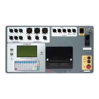
Vanguard Instruments CT-7000 S3 User Manual (137 pages)
DIGITAL CIRCUIT BREAKER ANALYZER
Brand:
Vanguard Instruments
| Category:
Measuring Instruments
| Size: 4.88 MB
Table of Contents
Table of Contents
3
Conventions Used in this Document
6
1 Introduction
7
General Description and Features
7
Option
8
Optional Features
9
Technical Specifications
10
Table 1. CT-7000 S3 Technical Specifications
10
CT-7000 S3 Controls and Indicators
11
Figure 1. CT-7000 S3 Controls and Indicators
11
Table 2. Functional Descriptions of CT-7000 S3 Controls and Indicators
12
2 Pre-Test Setup
13
LCD Screen Contrast Control
13
Printer Paper Control
13
Printer Paper
13
3 Operating Procedures
15
Cable Connections
15
Contact Cable Connections
15
Figure 2. Typical 3-Phase Circuit Breaker Connections
15
Figure 3. Typical Connections for Series Contact Circuit Breaker
16
Initiate Cable Connections
17
Figure 4. Typical DC Trip and DC Close Control Circuit Connection
17
Figure 5. Typical DC Trip and AC Close Control Circuit Connection
18
Online Timing Connections (with Optional Online Timing Feature)
19
Figure 6. On-Line Timing Probe Set (Part No. 9021-OT)
19
Figure 7. Typical Connections for Optional On-Line Timing Mode
20
Dual Ground Connections (with Optional Dual Ground Feature)
21
Figure 8. Typical Connections for Optional Dual Ground Testing Mode
21
Analog and Digital Voltage Monitoring Connections
22
Figure 9. Typical Analog and Digital Voltage Monitoring Connections
22
External Trigger Input Connections
23
Figure 10. Typical External Trigger Input Cable Connections
23
Digital Transducer Connection
24
Figure 11. Typical Digital Transducer Connection
24
Resistor Type Transducer Connection
25
Figure 12. Typical Resistor Type Transducer Connection
25
Changing Setup Parameters
26
Entering Test Record Header Information
26
Setting the Clock
29
Configuring Automatic or Manual Printing of Test Results
30
Setting the Units of Measure
31
Setting the OPEN Timing Analysis Points
32
Selecting the Contact Cycle Reading Frequency
35
Figure 13. Typical 50 Hz Tabulated Test Results
38
Figure 14. Typical 60 Hz Tabulated Test Results
38
Configuring the Channel Settings
39
Configuring the Contact Filter Settings
41
Figure 15. Contact Filter Setting Illustrations
42
Configuring the Transducer Encoder Filter Setting
43
Configuring the Digital Rotary Transducer Settings
45
Configuring the Resister Type Transducer Settings
47
Figure 16. Sample Resistor Type Transducer Setup Directory
53
Figure 17. Sample Timing Report Using a Resistor Type Transducer
54
Performing Circuit Breaker Timing Tests
55
Timing an OPEN Operation
56
Timing a CLOSE-OPEN Operation Using Contact Channel #1
59
Timing an OPEN-CLOSE-OPEN Operation
63
Figure 18. Typical O-C-O Test Results Graph
68
Figure 19. Typical Tabulated Test Results Printout for an O-C-O Operation
69
Figure 20. Typical On-Line Timing Test Graph Printout
70
Figure 21. Typical On-Line Timing Test Results Printout
71
Printing or Viewing Timing Results
72
Figure 22. Typical Tabulated Test Results Printout for a CLOSE Operation
74
Table 3. Descriptions of Tabulated Test Results Elements
75
Figure 23. Typical Test Results Graph (CB CLOSE Test)
76
Figure 24. Expansion Graph from 0Ms to 200Ms (CB CLOSE Test)
77
Figure 25. Typical O-C-O Test Results Graph
78
Figure 26. Typical Tabulated Test Results Printout for an O-C-O Operation
79
Figure 27. Graphical Interpretation of an OPEN Timing Shot
80
Figure 28. Graphical Interpretation of a CLOSE Timing Shot
80
Figure 29. Graphical Interpretations of an OPEN-CLOSE and CLOSE-OPEN Timing Shot
81
Working with Test Records
82
Saving a Timing Record in Flash EEPROM
82
Printing a Directory of Test Records Stored in the CT-7000 S3'S Memory
83
Figure 30. Sample Test Record Directory Printout
84
Printing a Directory of Test Records Stored in a USB Flash Drive
85
Recalling a Test Record from the Flash EEPROM
86
Restoring a Test Record from a USB Flash Drive
88
Ct-7000 S3 User's Manual Rev
88
Copying Test Records to a USB Flash Drive
90
Deleting Test Records from the Flash EEPROM
92
Deleting Test Records from a USB Flash Drive
95
Working with Test Plans
98
Recalling a Breaker Test Plan for Use
98
Figure 31. Typical Test Results Printout with Pass/Fail Indicators
100
Printing a Directory of Test Plans Stored in the CT-7000 S3'S Memory
101
Figure 32. Typical Test Plan Directory Printout
102
Printing a Directory of Test Plans Stored in a USB Flash Drive
103
Printing a Breaker Test Plan Stored in the CT-7000'S Memory
105
Printing a Breaker Test Plan Stored in a USB Flash Drive
107
Copying a Test Plan to a USB Flash Drive
109
Figure 33. Typical Breaker Test Plan Printout
111
Figure 34. Siemens SPS2 121 CLOSE Timing Illustration
112
Figure 35. Siemens SPS2 121 OPEN Timing Illustration
113
4 Diagnostics, Verification, and Troubleshooting
114
Performing a Slow-Close Test
114
Figure 36. Typical Slow-Close Test Results Printout
115
Performing a Transducer Self-Test
116
Testing the Cable Hookups
118
Printing Raw Test Record Data
120
Figure 37. Partial Data Points Printout
121
Troubleshooting Guide
122
5 Appendices
124
APPENDIX A - ITE Model 14.4K Circuit Breaker Timing Charts and Reports
124
Ct-7000 S3 User's Manual Rev
126
APPENDIX B - Siemens TCP Breaker Velocity Calculation
129
APPENDIX C - Siemens SPS2 Breaker Velocity Calculation
130
APPENDIX D - CT-7000 S3 Test Plan for Siemens SPS2
131
APPENDIX E - CT-7000 S3 Transducer Illustrations
132
APPENDIX F - CT-7000 S3 Accessories
135
Advertisement
Advertisement
Related Products
Vanguard Instruments CT-7500
Vanguard Instruments CT-7500-3
Vanguard Instruments CT-7500-6
Vanguard Instruments CT-7500-12
Vanguard Instruments CT-8000 S3
Vanguard Instruments CBPS-300
Vanguard Instruments CT-3500 S2
Vanguard Instruments CVT-765
Vanguard Instruments ATO-250
Vanguard Instruments ATRT-01 S3
Vanguard Instruments Categories
Measuring Instruments
Test Equipment
Power Supply
Adapter
Timer
More Vanguard Instruments Manuals
Login
Sign In
OR
Sign in with Facebook
Sign in with Google
Upload manual
Upload from disk
Upload from URL