Sign In
Upload
Manuals
Brands
Valleylab Manuals
Medical Equipment
Force FX-8C
Valleylab Force FX-8C Manuals
Manuals and User Guides for Valleylab Force FX-8C. We have
1
Valleylab Force FX-8C manual available for free PDF download: Service Manual
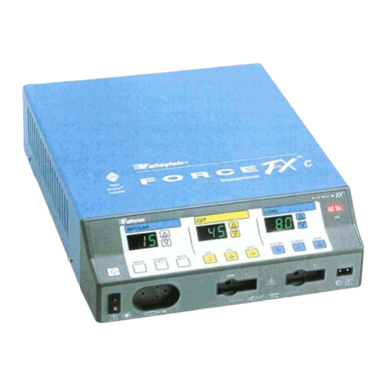
Valleylab Force FX-8C Service Manual (218 pages)
Electrosurgical Generator with Instant Response™ Technology
Brand:
Valleylab
| Category:
Medical Equipment
| Size: 2.51 MB
Table of Contents
Conventions Used in this Guide
3
Table of Contents
4
List of Figures
10
Section 1. Introduction
13
General Description
14
List of Components
15
Service Personnel Safety
15
General
15
Fire/Explosion Hazards
16
Electric Shock Hazards
17
Servicing
17
Calibration
18
Cleaning
18
Section 2. Controls, Indicators, and Receptacles
19
Front Panel
20
Bipolar Controls
21
Bipolar Instrument Receptacle
22
Monopolar Cut Controls
23
Monopolar Coag Controls
24
Monopolar Instrument Receptacles
25
REM Alarm Indicator
25
Rear Panel
26
Footswitch Receptacles
27
Monopolar Footswitch Receptacles
27
Bipolar Footswitch Receptacle
27
Power Entry Module
28
Activation Tone Volume Control
28
Option Panel
29
Section 3. Technical Specifications
31
Performance Characteristics
31
General
31
Dimensions and Weight
32
Operating Parameters
32
Transport and Storage
32
Duty Cycle
33
Internal Memory
33
Audio Volume
33
REM Contact Quality Monitor
34
Serial Port
35
RF Activation Port
35
Expansion Port
35
Low Frequency (50-60 Hz) Leakage Current
36
High Frequency (RF) Leakage Current
36
Input Power
37
Standards and IEC Classifications
38
Class I Equipment (IEC 601-1)
38
Type CF Equipment (IEC 601-1)/Defibrillator Proof
38
Drip Proof (IEC 601-2-2)
39
Electromagnetic Interference
39
Electromagnetic Compatibility (IEC 601-1-2 and IEC 601-2-2)
39
Voltage Transients (Emergency Generator Mains Transfer)
39
Output Characteristics
40
Maximum Output for Bipolar and Monopolar Modes
40
Maximum Output for Ultrasonic Electrosurgery
40
Available Power Settings in Watts
41
Output Waveforms
42
Output Power Vs. Resistance Graphs
44
Bipolar Graphs
44
Figure 3-2. Precise Bipolar Mode-Output Power Vs. Peak Voltage
44
Figure 3-4. Standard Bipolar Mode-Output Power Vs. Peak Voltage
45
Figure 3-6. Macrobipolar Mode-Output Power Vs. Peak Voltage
46
Monopolar Cut Graphs
47
Figure 3-8. Low Cut Mode-Output Power Vs. Peak Voltage
47
Figure 3-10. Pure Cut Mode-Output Power Vs. Peak Voltage
48
Figure 3-12. Blend Cut Mode-Output Power Vs. Peak Voltage
49
Monopolar Coag Graphs
50
Figure 3-14. Desiccate 1 Coag Mode-Output Power Vs. Peak Voltage
50
Figure 3-15. Desiccate 2 Coag Mode-Load Resistance Vs. Output Power
51
Figure 3-16. Desiccate 2 Coag Mode-Output Power Vs. Peak Voltage
51
Figure 3-17. Desiccate 3 Coag Mode-Load Resistance Vs. Output Power
52
Figure 3-18. Desiccate 3 Coag Mode-Output Power Vs. Peak Voltage
52
Figure 3-20. Fulgurate Coag Mode-Output Power Vs. Peak Voltage
53
Figure 3-22. LCF Fulgurate Mode-Output Power Vs. Peak Voltage
54
Figure 3-24. Spray Coag Mode-Output Power Vs. Peak Voltage
55
Section 4. Principles of Operation
57
Block Diagram
58
Functional Overview
59
Instant Response Technology
59
Ultrasonic Electrosurgery
59
Simultaneous Coag
59
REM Contact Quality Monitoring System
60
Control Board
61
Microcontrollers
61
Main Microcontroller
61
Feedback Microcontroller
62
Shared RAM
63
I/0 Expansion
63
Keyboard Interface and Activation Inputs
63
Power Supply Supervisor Circuit
64
A/D and D/A Conversion
64
Waveform Generation (T_ON ASIC)
64
T_ON Average Check
65
Audio Alarm
65
Serial Interface
65
Dosage Error Algorithm
66
Instant Response Algorithm
67
Front Panel
68
Membrane Keyboard
68
Power Switch
68
REM Connector/Switch
68
CEM Mechanism Switch
68
Display Board
69
RF Indicator Lamps
69
REM Indicators
69
LED and Seven-Segment Display Drivers
69
CEM Switch Circuit
70
Mode Selection and Power Control Switches
70
Footswitch Board
71
Footswitch Decode Circuit
71
Audio Circuit
72
Power Supply/Rf Board
73
Power Supply/Rf Board Interfaces
74
High Voltage Power Supply
74
Low Voltage Power Supply
77
RF Output Stage
77
Spark Control Circuit
80
RF Leakage Reduction Circuit
81
REM Circuit
81
Isobloc Circuit
81
Temperature Sense Circuits
82
Section 5. Setup, Tests, and Adjustments
85
Setting up the Generator
86
Connections for Bipolar or Macrobipolar Surgery
88
Setting the Bipolar Output
89
Connections for Monopolar Surgery
90
Selecting Cut and Coag Modes
92
Simultaneous Coag
92
Using Two Generators Simultaneously
93
Connecting the CUSA Handpiece with CEM Nosecone
94
Setting the Output Power
95
Simultaneous Coag with a CUSA System
95
Changing the Mode
95
Changing the Power Setting
95
Activating the Surgical Instrument
96
Periodic Safety Check
97
Recommended Test Equipment
97
Inspecting the Generator and Accessories
98
Inspecting the Internal Components
99
Testing the Generator
100
Verifying REM Function
101
Confirming Outputs
101
Check the Output for the Cut Modes
103
Check the Output for the Coag Modes
104
Checking Low Frequency Leakage Current and Ground Resistance
105
Checking High Frequency Leakage Current
107
Calibrating the Generator
108
Preparing for Calibration
109
Entering Calibration Mode
109
Exiting Calibration Mode
110
Verify the Generator Data
110
Adjust the Calendar
111
Adjust the Clock
112
Check and Adjust the REM Oscillator Frequency and Impedance
113
Check and Adjust the Current Sense Gain
114
Check and Adjust the Voltage Sense Gain
116
Check and Adjust the Reactance Gain
118
Check and Adjust the ECON Factor
120
Using the RS-232 Serial Port
124
Establish the Communications Link
124
Enter the Commands
125
Disconnect the Computer from the Generator
128
Section 6. Troubleshooting
129
Inspecting the Generator
129
Inspecting the Receptacles
130
Inspecting the Internal Components
131
Correcting Malfunctions
132
Responding to System Alarms
138
Correcting IC U3 Malfunctions
147
Correcting IC U6 Malfunctions
149
Correcting T_ON ASIC Malfunctions
151
Correcting Battery-Backed RAM Malfunctions
153
Section 7. Replacement Procedures
155
Interconnect Diagram
156
Battery Replacement
157
Control Board Replacement
158
Display Board Replacement
159
Remove the Display Board
159
Install the Display Board
160
Display Board Seven-Segment LED Replacement
161
Fan Replacement
162
Footswitch Board Replacement
162
Front Panel Replacement
163
Remove the Front Panel Assembly
163
Remove and Reinstall the Front Panel Components
163
Install the Front Panel Assembly
164
Front Panel REM Module Replacement
165
Front Panel Power Switch Replacement
166
Fuse Replacement
167
Replacing Fuses in the Fuse Drawer
167
Replacing the Fuse on the Power Supply/Rf Board
168
Left Front Heat Sink and Component Replacement
169
Remove the Left Front Heat Sink
169
Replace Left Front Heat Sink Components
170
Install the Left Front Heat Sink
170
Left Rear Heat Sink and Component Replacement
171
Remove the Left Rear Heat Sink
171
Replace Left Rear Heat Sink Components
172
Install the Left Rear Heat Sink
173
Right Heat Sink and Component Replacement
174
Remove the Right Heat Sink
174
Replace Right Heat Sink Components
175
Install the Right Heat Sink
176
Low Voltage Power Supply Replacement
177
Remove the Low Voltage Power Supply
177
Install the Low Voltage Power Supply
178
Power Entry Module Replacement
179
Remove the Power Entry Module
179
Install the Power Entry Module
180
Power Supply/Rf Board Replacement
181
Remove the Power Supply/Rf Board Assembly
181
Remove Components from the Old Board
182
Install Components on the New Board
183
Install the Power Supply/Rf Board Assembly
184
Section 8. Repair Policy and Procedures
185
Responsibility of the Manufacturer
185
Returning the Generator for Service
186
Obtain a Return Authorization Number
186
Clean the Generator
186
Ship the Generator
187
Returning Circuit Boards
187
Service Centers
188
Section 9. Service Parts
189
Ordering Replacement Parts
189
Generator Assembly
190
Parts List
192
Front Panel Assembly
194
Parts List
196
Control Board Components
197
Display Board Components
198
Footswitch Board Components
199
Power Supply/Rf Board Assembly
202
Parts List
204
Power Supply/Rf Board Components
206
Advertisement
Advertisement
Related Products
Valleylab ForceTriad
Valleylab Force 2
Valleylab Force 30
Valleylab Force 40
Valleylab Force FX-C
Valleylab FORCE 4
Valleylab Force EZ - C Series
Valleylab Force 2-2 PCH
Valleylab Force 2-8 PCH
Valleylab Force2
Valleylab Categories
Medical Equipment
Portable Generator
Inverter
More Valleylab Manuals
Login
Sign In
OR
Sign in with Facebook
Sign in with Google
Upload manual
Upload from disk
Upload from URL