Sign In
Upload
Manuals
Brands
Vaisala Manuals
Measuring Instruments
MGP261
Vaisala MGP261 Multigas Probe Manuals
Manuals and User Guides for Vaisala MGP261 Multigas Probe. We have
2
Vaisala MGP261 Multigas Probe manuals available for free PDF download: Installation And Safety Manual, User Manual
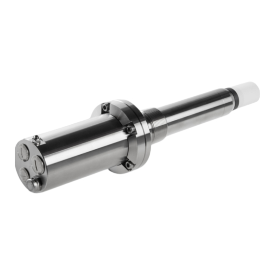
Vaisala MGP261 Installation And Safety Manual (208 pages)
Multigas Probe for Methane, Carbon Dioxide, and Humidity Measurement
Brand:
Vaisala
| Category:
Measuring Instruments
| Size: 7.44 MB
Table of Contents
Hazardous Area
8
Basic Features and Options
9
Maintenance
12
Installation Overview
14
Before Starting Installation
16
Wiring Diagram
19
Weitere Informationen
21
Plus D'informations
35
Présentation de L'installation
41
Avant de Procéder à L'installation
44
Schéma de Câblage
48
Meer Informatie
49
Más Información
63
Mantenimiento
66
Descripción General de la Instalación
68
Antes de Iniciar la Instalación
71
Diagrama de Cableado
75
Mais Informações
77
Visão Geral da Instalação
82
Diagrama de Fiação
89
Altre Informazioni
91
Manutenzione
94
Panoramica Dell'installazione
96
Prima DI Iniziare L'installazione
99
Schema DI Cablaggio
103
További InformáCIók
105
Bekötési Rajz
117
Další Informace
119
Schéma Zapojení
129
Więcej Informacji
131
Schemat Połączeń
144
Mer Information
169
Mer Informasjon
181
Yderligere Oplysninger
193
Advertisement
Vaisala MGP261 User Manual (90 pages)
Multigas probe for methane, carbon dioxide, and humidity measurement
Brand:
Vaisala
| Category:
Measuring Instruments
| Size: 4.7 MB
Table of Contents
Table of Contents
3
1 About this Document
9
Version Information
9
Related Manuals
9
Documentation Conventions
9
Table 1 Document Versions
9
Table 2 Related Manuals
9
Trademarks
10
2 Product Overview
11
Introduction to MGP261
11
Basic Features and Options
11
Hazardous Area Safety
11
Measurement Parameters
12
Wet Basis and Dry Basis Measurement Output
12
Figure Output Parameter Selections in Vaisala Insight PC Software
12
Table 3 MGP261 Measurement Parameters
12
Installation Type
13
Process Flow Range and Installation Type
13
Connectivity to Vaisala Insight Software
13
Probe Parts
15
Figure 2 MGP261 Probe Parts (Closed and Opened View)
15
Cable Gland Options and Lead-Throughs
16
Figure 3 Cable Gland Options and Lead-Throughs
16
Measurement Principle
17
Figure 4 Probe Cuvette with Mirror and Sensor Chips
17
Figure 5 Measurement in the Measurement Cuvette
18
Using MGP261 in Hazardous Locations
19
Guidelines for Safe Use in Hazardous Conditions
19
Figure 6 MGP261 Probe Ga/Gb Division
19
Table 4 Screw Terminal Wiring Requirements
20
Table 5 Intrinsic Safe IIB Output Parameters
20
3 Installation
22
Overview
22
Process Flow Range and Installation Type
22
NPT 1.5" Thread Test Plug 257525SP
23
Installation Preparations
23
Figure 7 NPT 1.5" Thread Test Plug
23
Installation Option: Ball Valve Installation
24
Figure 8 MGP261 Installation Example with Wiring Routes and Recommended Orientation and Depth
24
Installation Option: Flow-Through Adapter Installation
25
Figure 9 MGP261 in Flow-Through Adapter 258877
25
MGP261 Dimensions
26
Recommended Installation Position on Pipeline
26
Figure 10 MGP261 Dimensions in Millimeters and Inches
26
Figure 11 Recommended MGP261 Installation Position on Pipeline
26
Gas Safety During Installation
27
Preparing Probe for Installation
28
Inserting Probe into Process and Opening Connection Box
29
Wiring
30
Figure 12 MGP261 Screw Terminal Markings and Cable Routes
30
Figure 13 MGP261 Wiring Diagram
31
Wiring Diagram
31
Finalizing Installation
32
Attaching Flow-Through Adapter to MGP261
33
Installation Type Configuration in Insight
35
Figure 14 Installation Type Selection in Insight
35
4 Operating with Insight Software
36
Vaisala Insight Software
36
Basic and Advanced User Modes
36
Connecting to Insight Software
37
Figure 15 Connecting Probe to Insight
37
Installing the Driver for the USB Service Cable
38
Insight Main View
39
Figure 16 Insight Main Menu and Settings
39
5 Modbus
40
Table 6 Default Modbus Serial Communication Settings
40
Configuring Modbus Communication Settings with Insight
41
Figure 17 Modbus Communication Settings in Insight PC Software
41
6 Analog Output Configuration
42
Overview
42
Configuring Analog Outputs with Modbus
42
Configuring Analog Outputs with Insight
42
Figure 18 Analog Output Configuration Options in Insight
42
Changing Units in Insight
43
Figure 19 Unit Selection in Insight
43
Wet Basis and Dry Basis Measurement Parameters
44
Figure 20 Output Parameter Selections in Vaisala Insight PC Software
44
7 Environmental Compensation
45
Overview
45
Temperature Compensation
45
Pressure Compensation
45
Compensation Mode During Calibration
46
Configuring Environmental Compensations with Modbus
46
Configuring Environmental Compensations with Insight
46
Figure 21 Measurement Menu View in Insight PC Software
47
Configuring Setpoint Values for Compensations with Insight
48
Using Compensation Received from External Temperature or Pressure Sensor
48
Using Probe Measurement as Temperature Compensation
48
Configuring Input from External Analog Pressure or Temperature Sensor
49
Figure 22 Analog Input 1 Configuration Menu in Insight
49
8 Calibration
51
Calibration Overview
51
Compensation Mode During Calibration
52
Flow-Through Adapter
52
Figure 23 Flow-Through Adapter 258877
52
Calibration and Adjustment with Insight PC Software
54
Figure 24 Calibration Menu View in Insight PC Software
54
Example: 2-Point Adjustment with Zero Point Adjustment
55
Zero Point Adjustment
55
Calibrating and Adjusting Methane (CH ) Measurement
56
Figure 25 Zero Point Adjustment Tab
56
Calibrating and Adjusting Carbon Dioxide (CO ) Measurement
57
Calibrating and Adjusting Temperature Measurement
58
Figure 26 Temperature Adjustment View in Insight
58
9 Maintenance
60
Filter Change
60
Figure 27 Replacing Filter
60
Removing Probe from Process
61
Cleaning the Probe
62
Sending Probe to Vaisala
63
10 Technical Data
64
Specifications
64
Table 7 Measurement Performance
64
Table 8 Operating Environment
65
Table 9 Compliance
65
Table 10 Inputs and Outputs
65
Table 11 Mechanical Specification
66
Table 12 Options and Accessories
66
Wetted Parts Material Information
67
MGP261 Dimensions
68
Figure 28 MGP261 Dimensions in Millimeters and Inches
68
Flow-Through Adapter Dimensions
69
Figure 29 Flow-Through Adapter Dimensions with MGP261 Probe
69
Figure 30 Flow-Through Adapter Mounting Plate Dimensions
69
Modbus Registers
70
Measurement Data
70
Table 13 Modbus Measurement Data Registers (Read-Only)
70
Appendix A
70
Configuration Registers
72
Table 14 Modbus Configuration Data Registers (Writable)
72
A.1.2 Configuration Registers
72
Status Registers
82
Table 15 Modbus Status Data Registers (Read-Only)
82
A.1.3 Status Registers
82
Table 16 Error Codes in Register 0200
83
Hex (Status Code Low)
83
Table 17 Error Codes in Register 0202 Hex (Status Code High)
84
Device Identification Objects
85
Table 18 Device Identification Objects
85
Warranty
87
Technical Support
87
Recycling
87
Advertisement
Related Products
Vaisala MGP260 Series
Vaisala MGP241
Vaisala M212551EN-B
Vaisala MMP8
Vaisala MI70
Vaisala MW11
Vaisala HUMICAP MM70
Vaisala HUMICAP MMT310
Vaisala MOG100
Vaisala MHT410
Vaisala Categories
Transmitter
Measuring Instruments
Accessories
Weather Station
Test Equipment
More Vaisala Manuals
Login
Sign In
OR
Sign in with Facebook
Sign in with Google
Upload manual
Upload from disk
Upload from URL