Sign In
Upload
Manuals
Brands
Turbosound Manuals
Speaker System
Aspect TA-890
Turbosound Aspect TA-890 Manuals
Manuals and User Guides for Turbosound Aspect TA-890. We have
1
Turbosound Aspect TA-890 manual available for free PDF download: User Manual
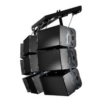
Turbosound Aspect TA-890 User Manual (95 pages)
Modular point source loudspeaker system
Brand:
Turbosound
| Category:
Speaker System
| Size: 7.17 MB
Table of Contents
Table of Contents
2
EC Declaration of Conformity
6
User Manual TA
6
Introduction
7
Turbosound Aspect System Concepts
7
The Turbosound Polyhorn
7
Aspect TA-890 Turnkey System Concept
9
The Loudspeaker Management System (LMS) Concept
10
LMS-D24, LMS-D26 and LMS-D6 Loudspeaker Management Systems
10
Amplifier Racks
10
Power Amplifiers
10
Digital Controllers
11
Aspect Loudspeaker Components
11
TA-890L Low Frequency Enclosure
11
TSW-218 Subwoofer
12
TA-890H MID-High Enclosure
12
Transportation
14
Aspect Flying Systems
15
Flying and Stacking
16
Overview
16
Gigmate™ Acoustic Simulation
17
Setting up a Venue - Overview
17
Running Turbosound Gigmate™ / EASE Focus for the First Time
18
Designing a System
20
Changing the System
23
Safety Notes on Rigging
25
Sample Certificate of Load Test
26
Flying Hardware
27
Wide and Narrow Flybar Settings
27
Figure 1. Single A-System Flybar FB-890/1A
28
Figure 2. Double A-System Flybar FB-890/2A
29
Figue 3. Triple 'A' System Flybar FB-890A/3W
30
FC-890 Flying Chains
31
TS-890 Tilting Straps
31
Three-Wide Hang Using MB-890, EB-890, FB-890/2A and FB-890/1A
32
Four-Wide Hang Using MB-890 and FB-890/2A
33
Integral Flying Hardware
34
A' System Flygear
34
1 Drop Link
35
Connecting Cabinets - 'A' System
35
Connecting Flying Chains to the Cabinet
35
Figure 1 – Insert Cabinet Link Figure 2 – Release Swing Latch
35
2 Swing Latch
35
Setting Vertical Angles - 'A' System
36
Attaching the Tilt Straps
37
Aiming - Directivity of the Stack
38
Bass Enclosure Arraying
38
Turbobass Directivity
38
The Typical Left to Right Problem
40
Bass in a Line
41
Creating Directional Bass Arrays
41
Fanned Bass
42
Bessel Array
43
General Observations of Long Lines of Bass
43
End Firing Array
44
Summing up
45
Ground Stacking
46
LMS SERIES Loudspeaker Management Systems
47
Introduction
47
General Features & Facilities
47
Unpacking
47
Mechanical Installation
47
LMS-D6 Front Panel Functions
48
LMS-D6 Rear Panel Functions
49
Mains Power
49
Voltage Setting
50
Safety Earthing
50
AC Power Fusing
50
Powering up
50
Audio Connections
51
Input and Output Connector Wiring
51
Time Correction for Loudspeaker Driver Placement
51
LMS-D24 and D26 LOUDSPEAKER MANAGEMENT SYSTEMS
52
Features
52
Front Panel Functions
53
Rear Panel Functions
55
Operating the LMS-D24 and D26
56
Starting up
56
Selecting a Factory Preset
56
Creating a Crossover
56
Navigation and Viewing Parameters
57
Navigation
58
Preset Recall
59
Preset Store
60
DSP Processing Layout
61
Input DSP Block Diagram
61
Output DSP Block Diagram
61
Stereo / Mono Formats
61
DSP Processing
62
Input Channels
62
Parametric Equalisation
64
High and Low Shelving Filters
64
Parametric Filters
64
Output Channels
65
Gain and Polarity
65
Delay
65
High and Low Pass Filters
66
Parametric Equalisation
67
Limiters
68
Routing
68
Utilities
69
Utility Functions
69
Rear Panel Functions
70
AMP-890 Aspect System Amplification Rack
71
Racking, Cables and Connections
71
Options
72
Input Connections
72
Figure 1. Amplifier Rack Signal Wiring
73
Output Connections
73
Figure 2. MID-High Outputs
74
Figure 3. Bass Outputs
74
Break-Out Cables - NL4 Bass
75
Break-Out Cables - NL8 MID-High
76
Extension Cables
76
Mains Connections
77
T-25 and T-45 High Efficiency Audio Power Amplifiers
78
General Features & Facilities
78
Front Panel Functions T-25
79
Front Panel Functions T-45
80
Mechanical Installation
81
Mains Power
81
Powering up
81
Safety Earthing
81
Voltage Setting
82
Voltage Range
82
Audio Connections & Controls
82
Polarity
83
Input Impedance
83
Gain and Sensitivity Settings
83
Attenuation & Gain Setting
84
Output Connections
84
Damping Factor
84
Long Speaker Lines
85
The Cooling System
85
Maintenance
86
To Rotate the Horn Moulding from 'A' Mode to 'B' Mode
87
To Rotate the Horn Moulding from 'B' Mode to 'A' Mode
88
Removal of the High Frequency Driver
88
Removal of the High-MID Frequency Driver
89
Removal of the Low-MID Frequency Drive Units
90
General Maintenance
90
Flying Hardware
90
Paintwork
91
Technical Specifications
93
Warranty
94
Advertisement
Advertisement
Related Products
Turbosound TBV123-AN
Turbosound TLX215L
Turbosound TQ8-SB
Turbosound TQ15-YB
Turbosound TQ12-YB
Turbosound Prague TPZ122/64
Turbosound Prague TPZ153/64
Turbosound Prague TPZ152/64
Turbosound Prague TPA152/64/95-WH
Turbosound Prague TPA152/64/95
Turbosound Categories
Speakers
Speaker System
Subwoofer
Racks & Stands
TV Mount
More Turbosound Manuals
Login
Sign In
OR
Sign in with Facebook
Sign in with Google
Upload manual
Upload from disk
Upload from URL