Sign In
Upload
Manuals
Brands
Trane Manuals
Touch Panel
Symbio 800
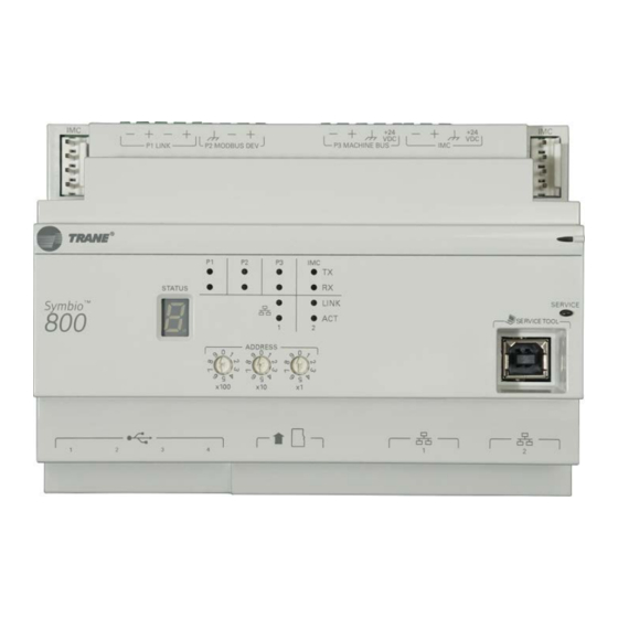
Trane Symbio 800 Manuals
Manuals and User Guides for Trane Symbio 800. We have
4
Trane Symbio 800 manuals available for free PDF download: Installation, Operation And Maintenance Manual, Integration Manual, Installation Instructions Manual, Installation Manual
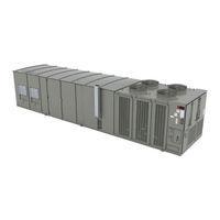
Trane Symbio 800 Installation, Operation And Maintenance Manual (164 pages)
Commercial Packaged Rooftop Air Conditioners with VAV or SZVAV Controls and eFlex/ eDrive
Brand:
Trane
| Category:
Air Conditioner
| Size: 12.07 MB
Table of Contents
Table of Contents
4
Model Number Description
7
20 To 75 Tons, Air Cooled
7
90 To 130 Tons, Air Cooled
10
General Information
12
Unit Nameplate
12
Compressor Nameplate
12
Gas Heat Nameplate
12
Unit Description
12
Pre-Installation
13
Unit Inspection
13
Exterior Inspection
13
Damage
13
Repair
13
Storage
13
Unit Clearances
13
Information
14
Factory Warranty Information
14
All Unit Installations
14
Additional Requirements for Units
14
Requiring Disassembly
14
Installation Checklist
15
General Checklist
15
Units)
15
Main Electrical Power
15
Requirements
15
Field Installed Control Wiring
15
Requirements for Gas Heat
15
Requirements for Hot Water Heat
15
(Slh_)
15
Requirements for Steam Heat
16
Return Fans)
16
Requirements for Modulating
16
Reheat
16
Dimensional Data
17
Center of Gravity
24
Electrical Entry Details
25
Minimum Required Clearance
27
Weights
28
Installation
30
Roof Curb and Ductwork
30
Pitch Pocket Location
30
Unit Rigging and Placement
31
General Installation Requirements
32
Rigging the Unit
32
O/A Pressure Sensor and Tubing Installation
33
Main Electrical Power
33
Field Installed Control Wiring
33
Electric Heat Units
33
Gas Heat (SFH_)
33
Hot Water Heat (SLH_)
33
Steam Heat (SSH_)
33
O/A Pressure Sensor and Tubing
33
Modulating Reheat (S_H_)
33
Condensate Drain Connections
34
Units with Gas Furnace
34
Removing Supply and Relief/Return Fan Shipping Channels (Motors >5 Hp)
34
Spring Isolators
34
Optional DDP Supply Fan Shipping Channel Removal and Isolator Spring
35
Adjustment
35
Shipping Tie down and Isolator Spring Adjustment
35
O/A Sensor and Tubing Installation
39
Gas Heat Units (SFH_)
40
Connecting the Gas Supply Line to the Furnace Gas Train
41
Flue Assembly Installation
45
General Coil Piping and Connection
45
Recommendations
45
Hot Water Heat Units (SLH_)
46
Steam Heat Units
46
Disconnect Switch with External
49
Handle
49
Electric Heat Units (SEH_)
50
Main Unit Power Wiring
51
Electrical Service Sizing
53
Set 1: Cooling Only Rooftop Units and Cooling with Gas Heat or Hydronic Heat Rooftop Units
53
Set 2: Rooftop Units with Electric
54
Heat
54
Field Installed Control Wiring
58
Controls Using 24 VAC
59
Transformer for Expansion Module
59
Controls Using DC Analog Input
59
Outputs
59
Variable Air Volume System
60
Controls
60
Discharge Temperature Control
60
Changeover Contacts
60
Remote Zone Sensor
60
(Baysens073*)
60
(Baysens074*)
60
Equipment Stop
60
Ventilation Override Mode (VOM)
60
Contacts
60
Emergency Stop Switch
61
Occupied/Unoccupied Contacts
61
Wall or Duct Mount Humidity Sensor
61
Baysens037*)
61
Unit Replacement
62
Electrical Connection
62
Main Electrical Power
63
SEHF Units with 200V or 230V
63
Electric Heat
63
Field-Installed Control Wiring
63
Requirements for Gas Heat
63
Requirements for Hot Water Heat
63
(Slh*)
63
Requirements for Steam Heat
63
(Ssh*)
63
Space Pressure Sensor and Tubing
63
Condensate Drain Connections
64
Connections
64
Installation of New Units
64
Unit Startup
68
Sequence of Operation
68
Stop/Off/Auto
68
Occupancy
68
Performance Data
69
Supply Fan Performance
69
1700 Rpm
70
1400 Rpm
73
1300 Rpm
74
Airflow, CFM
74
I I M M P P O O R R T T a a N N T T : : Maximum Static Pressure Leaving the
74
Rooftop Is 4.0" H 2 O Positive. the Static
74
Pressure Drops from the Supply Fan to the Space Cannot Exceed 4.0" H
74
Pressure Drop Tables
91
Component Static Pressure
94
Drops
94
Fan Drive Selections
97
Pressure Curves
102
Economizer and Relief Air Damper
110
Adjustment
110
Exhaust Air Dampers
110
Outside Air and Return Air Damper
110
Operation
110
Travel
111
Compressor Startup (All Systems)
113
Refrigerant Charging
114
Heaters
115
Sounds
115
Electronic Compressor Protection
115
Module (CPM)
115
Electronic Expansion Valves
118
Measuring Superheat
119
Charging by Subcooling
119
Measuring Subcooling
119
Low Ambient Options
119
Operation
119
Standard Ambient Condenser
120
Fans
120
Low Ambient Condenser Fans
120
Electric, Steam and Hot Water Start
120
(Variable Air Volume Systems)
120
Electric, Steam and Hot Water Start
121
Gas Furnace Startup
122
Staged, Modulating, and Ultra
122
Modulating
122
Two Stage Gas Furnace
122
Ultra Modulating Gas Furnace
126
Ultra Modulating Burner Setup
127
Final Unit Checkout
129
Trane Startup Checklist
130
Changeover Map
133
Service and Maintenance
135
Fan Belt Adjustment
137
Scroll Compressor Replacement
138
Refrigeration System
139
CSHD and CSHN Compressors
140
Electrical Phasing
142
Ton Eflex™ Variable Speed
142
Tandem
142
Precision Suction Restrictor
142
VFD Programming Parameters
143
(Supply/Relief)
143
Eflex™ Compressor VFD Programming
151
Parameters
151
Monthly Maintenance
152
Filters
152
Cooling Season
152
Heating Season
153
Coil Cleaning
154
Refrigerant Coils
154
Steam or Hot Water Coils
155
Microchannel Condenser Coil Repair and Replacement
155
Fall Restraint
155
Final Process
155
Unit Wiring Diagram Numbers
158
Warranty and Liability Clause
160
Accessories
160
Advertisement
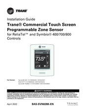
Trane Symbio 800 Installation Manual (29 pages)
Commercial Touch Screen Programmable Zone Sensor
Brand:
Trane
| Category:
Touch Panel
| Size: 2.25 MB
Table of Contents
Table of Contents
4
Equipment/Software Supported
5
Reliatel
5
Symbio 400
5
Symbio 700
5
Symbio 800
5
Installation
6
Location Guidelines
6
Installing the Sensor
6
Zone Sensor Wiring
7
Communication Wire
7
External Sensor Inputs
7
Reliatel Systems
8
Symbio 400/Symbio 400B Systems
9
Symbio 700 Systems
11
Symbio 800 Systems
12
General Information
13
Configuring Settings on the Home Screen
14
Cool/Heat Mode
14
Fan Mode
14
Schedule Menu
14
Override
14
Touch Button Legend
14
Menu Navigation
15
Interface Flowchart, Part 1
15
Interface Flowchart, Part 2
16
Interface Flowchart, Part 3
17
Interface Flowchart, Part 4
18
Network
18
Menu Definitions
19
Configuration
19
Setpoints
21
Display
22
Clock, Schedule, Setpoints, and Options
23
Service View
24
Installation Instructions
25
Symbio 400
25
Reliatel BCI-R
25
Zone Sensor Configuration
26
Symbio 700/800
26
Reliatel Field Upgrade Procedure
27
BCI-R Initialization Procedure
27
Specifications
28
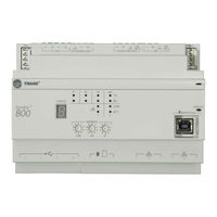
Trane Symbio 800 Installation Instructions Manual (32 pages)
Control Upgrade Kit For UC800 AdaptiView Display
Brand:
Trane
| Category:
Controller
| Size: 6.2 MB
Table of Contents
Table of Contents
4
General Information
5
Summary of UC800 Display Upgrade
5
Unit Model Number
5
Model Number Descriptions
6
Getting Started
7
Nameplate
7
Symbio 800 Adaptiview Display Upgrade Kit Contents
7
Running the IPC Bus
7
Installation
9
Installation of UC800 Control Upgrade
9
Check the Configuration and Set-Points in the Adaptview Display
9
Save the Adaptview Configuration and Set-Points
9
Upgrading Display Firmware
10
Update the Display Original X-CODE to Symbio Display X-CODE
13
Shut down Power
13
Remove the Existing UC800 Controller and In- Stall New Symbio 800 Controller
13
Remove the Existing Display and Install New
14
Display (When Required)
14
Solid State Oil Heater Relay Installation
14
Mounting Location
14
Installation
15
Installation of Options
16
LON Option
16
Communication Option
16
Communication Device Mounting
17
Water Flow Measurement Options
18
Energy Meter Option Installation
20
Expansion Module Option
21
Starter up
22
Restoring System Power
22
Programming
23
Programming the Symbio 800 Adaptiview
23
Start-Up
26
Wiring Diagrams
27
Advertisement
Trane Symbio 800 Integration Manual (32 pages)
BACnet and Modbus Integration
Brand:
Trane
| Category:
Industrial Equipment
| Size: 5.42 MB
Table of Contents
Warnings, Cautions, and Notices
2
Revision History
3
Table of Contents
4
Overview
5
Purpose
5
Symbio™ 800 Controller Overview
5
Communication Options
5
Units of Measure
5
Communication Setup and Configuration
6
Service Tool for Symbio™ 800 Configuration
6
Connecting to the Symbio™ 800 Web Interface
6
Bacnet ® Protocol Configuration
8
Bacnet MS/TP Protocol Settings
8
Bacnet ® IP (Ethernet or Wi-Fi Connectivity)
9
Manually Change Symbio™ 800 Bacnet ® Device ID
12
Air-Fi ® Wireless
14
Bacnet Points List
15
Download
15
Object Naming Conventions
15
Recycled Points
15
Modbus Protocol Configuration
19
Modbus Protocol Settings
19
Modbus Wiring
20
Modbus TCP (Ethernet)
20
Modbus Points List
22
Download
22
Object Naming Conventions
22
Recycled Points
22
Appendix A. Arbitration
26
Appendix B. Symbio™ 800 Controller Layout
27
Advertisement
Related Products
Trane 80
Trane XR 80 TUD1A060A9241A
Trane XR 80 TUD1B060A9361A
Trane XR 80 TUD1B080A9241A
Trane XR 80 TUD1B080A9481A
Trane XR 80 TUD1C080A9601A
Trane XR 80 TUD1D120A9601A
Trane XR 80 TUD1D140A9601A
Trane Symbio 210
Trane Symbio 800 Control Upgrade Kit
Trane Categories
Air Conditioner
Heat Pump
Chiller
Air Handlers
Furnace
More Trane Manuals
Login
Sign In
OR
Sign in with Facebook
Sign in with Google
Upload manual
Upload from disk
Upload from URL