Sign In
Upload
Manuals
Brands
Trane Manuals
Chiller
R Series
Trane R Series Manuals
Manuals and User Guides for Trane R Series. We have
8
Trane R Series manuals available for free PDF download: Installation Operation & Maintenance, Installation, Operation And Maintenance Manual, Diagnostic Troubleshooting Repair
Trane R Series Installation Operation & Maintenance (168 pages)
175-450 ton units (60 Hz); 125-450 ton units (50 Hz)
Brand:
Trane
| Category:
Chiller
| Size: 5.66 MB
Table of Contents
Important Notices
3
Refrigerant Emission Control
4
Warnings and Cautions
5
Table of Contents
7
General Information
9
Literature Change History
9
Unit Identification - Nameplates
9
Unit Inspection
9
Inspection Checklist
9
Unit Description
10
Model Number Coding System
10
Loose Parts Inventory
10
Model Number for RTHC Chiller
10
RTHC Compressor Model Number
12
RTHC Starter/Control Panel Model Number
13
Starter/Control Panel Model Number for RTHC
13
Compressor Model Number for RTHC
13
Component Location for Typical RTHC Unit
15
Component Location for Typical RTHC Unit (Back View)
16
Installation Overview
17
Installation Responsibility Chart for RTHC Units
17
General Data
18
Unit Designator
19
Installation - Mechanical
23
Storage
23
Vibration Eliminators
23
Location Requirements
23
Recommended Operating and Service Clearances
24
Ventilation
24
Water Drainage
24
Access Restrictions
24
Moving and Rigging
25
Unit Weights and Dimensions for Rigging
25
Lifting Procedure
27
Lifting the Unit
28
Alternate Moving Method
29
Isolation Pads
29
Isolator Pad Placement
30
Acceptable Pad Configurations
30
Oil Separator with Shipping Bracket Installed
30
Reversing Water Boxes
31
Water Piping
31
Piping Connections
31
Unit Leveling
31
Condenser and Evaporator Water Connections
32
Connection Configuration (Left or Right Hand)
32
Evaporator and Condenser Data
38
Water Pressure Drop Data
39
Condenser Pressure Drop
39
Making Grooved Pipe Connections
45
Leaving Chilled Water Piping
45
Vents and Drains
45
Entering Chilled Water Piping
45
Leaving Condenser Water Piping
46
Condenser Water Regulating Valve Adjustment
46
Water Treatment
46
Water Pressure Gauges and Thermometers
47
Water Pressure Relief Valves
47
Flow Sensing Devices
47
Refrigerant Pressure Relief Valve Venting
48
Relief Valve Locations
48
Thermal Insulation
49
Pressure Relief Valve Data
49
Typical RTHC Insulation Requirements
50
Recommended Insulation Types
50
Installation - Electrical
51
General Recommendations
51
Power Supply Wiring
51
Electrical Panel Power Supply
51
Water Pump Power Supply
51
Wire Selection Chart for Starter Panels
52
Electrical Installation
52
Other Supply Power Components
53
Compressor Motor Phase Sequencing
53
Terminal Lugs
53
Compressor Motor Power Wiring
53
Correcting Improper Electrical Phase Sequence
53
Minimum Circuit Ampacity (MCA)
54
Maximum Fuse/Circuit Breaker Size
54
Recommended Field Connection Starter Lug Sizes
54
Application of Solid-State Starters
54
Solid-State Starter Controller Settings
55
Solid State Starter Selections
56
Precautions When Using Solid-State Starters
56
Solid State Starter Connections
57
Motor Terminal Junction Box Wiring (Wye Delta Starter)
59
Module Connections for Interconnecting Wiring
59
Interconnecting Wiring (Field Wiring Required)
59
Chilled Water Flow Interlock
60
Condenser Water Pump Control
60
Condenser Water Flow Interlock
60
Outdoor Air Temperature Sensor
60
Tracer Controlled Contact
61
External Base Loading
61
Head Relief Request Contact
61
Ice Machine Control
61
Tracer Temperature Sensor Option
62
Percent Condenser Pressure Output
62
Compressor Percent RLA Output
62
Operating Principles - Mechanical
63
General
63
RTHC - Basic Unit Components
63
Refrigeration (Cooling) Cycle
64
Cycle Description
64
Pressure /Enthalpy Curve
65
Refrigerant Flow Diagram
65
Compressor Description
66
RTHC Compressor
66
Compressor Motor
67
Compressor Rotors
67
Slide Valve Movement
67
Oil Management System
67
Oil Flow Diagram
68
Oil Flow Protection
68
Lubricant Recovery
69
Oil Filter
69
Compressor Bearing Oil Supply
69
Compressor Rotor Oil Supply
69
Oil Cooler
70
UCP2 Microprocessor Control System
71
Control System Block Diagram
72
Chiller Module - 1U1
72
Stepper Module - 1U3
73
Printer Interface Module - 1U7
73
Clear Language Display (CLD) - 1U4
73
Options Module - 1U5
73
COMM 3 or COMM 4 (Tracer Interface)- 1U6
73
Clear Language Display Key Assignments
74
Settings Groups
74
Key Functions
74
Report Groups
74
Communications and Settings Storage
75
No Communications - Data Not Valid
75
Chiller Report
76
Custom Report Group - Programming Instructions
76
Report Already in Custom Menu
76
User Defined Custom Report
76
Operating Modes
78
Current Limit Setpoint and Source
79
Outdoor Temperature (Standard Report)
79
Ice Termination Setpoint/Ice Termination Setpoint Source
79
ASHRAE Guideline 3 Report Menu
80
Refrigerant Monitor (ASHRAE Report)
80
Refrigerant Report
82
Electronic Expansion Valve Position
82
Report Heading
82
Evaporator and Condenser Refrigerant Pressure
82
Compressor Report
83
Operator Settings
84
Operator Settings Group Heading
84
Menu Settings Password
84
Time of Day Setting
84
Front Panel Current Limit Setpoint
85
Print Report
85
Front Panel Chilled Water Setpoint
85
Chilled Water Reset Type
85
Start Reset Setpoint
86
Max Reset Setpoint
86
Chilled Water Setpoint Source
86
Setpoint Source Override
86
Keypad/Display Lockout
87
Service Settings (Non Password Protected Service Settings Group)
87
Display Menu Headings
88
Clear Custom Menu
88
Language Setting
88
Differential to Start
88
Evap/Cond Pump off Delay Time
89
Printer Setups
89
Field Startup Group Password Request
90
Machine Configuration Group Password Request
90
Clear Restart Inhibit Timer
90
Service Settings (Password Protected Field Startup Group)
90
Field Startup Group Heading
91
Keypad/Display Lock Feature Enable
91
Password Duration Time
91
Power up Start Delay Time
91
Design Delta Temperature
92
Condenser Limit Setpoint
92
Leaving Water Temperature Cutout Setpoint
92
Maximum Restart Inhibit Timer Setting
92
Phase Unbalance Limit Enable
93
Soft Load Current Limit Rate of Change
93
Momentary Power Loss Protection Enable
93
LWT Control Proportional Gain
93
Liquid Level Control Proportional Gain
94
Machine Configuration Group Heading
94
Liquid Level Control Integral Reset Time
94
Refrigerant Monitor Type
94
Service Settings (Password Protected Machine Configuration Group)
94
Rated Load Amps
95
Motor Heating Constant
95
Recommended Motor Heating Constant Settings
95
Recommended Max. Acceleration Timer Settings
96
Acceleration Time out Action
97
External Current Limit Setpoint Option
97
High Pressure Cutout Setting
97
Line Voltage Sensing Option
97
Tracer Communication Interface Module Option
98
Printer Option
98
Ice Building Option
98
Programmable Relay Assignments
98
Refrigerant Pressure Analog Output Option
99
Min Delta Pressure Calibration
99
Condenser Pressure Analog Output
99
Max Delta Pressure Calibration
100
Service Tests
100
Service Settings (Password Protected Refrigerant Monitor Settings Group)
100
Service Settings (Password Protected Refrigerant Monitor Calibration Group)
100
Service Tools Group Password Request
101
Service Tests Menu Heading
101
Chilled Water Pump
101
Condenser Water Flow Switch Status
101
Expansion Valve Test
102
EXV Control Mode/Exv Position Commands
102
EXV Position/Percent and Steps Open
102
Manual Loading/Unloading Duty Cycle
103
Oil Flow Delta Pressure Switch Status
103
Oil Return Gas Pump Fill Solenoid Valve
103
Oil Return Gas Pump Drain Solenoid
103
Module Software Revision Levels
104
Factory Settings
104
General Factory Settings
104
Diagnostics
106
Diagnostics Group Header Display Screens
106
Clearing Diagnostics
108
Unit Start-Up
109
Daily Unit Start-Up
109
Limit Conditions
111
Seasonal Unit Start-Up Procedure
111
Daily Unit Shutdown
113
Seasonal Unit Shutdown
113
Unit Is Preparing to Shutdown
113
Weekly Maintenance and Checks
115
Monthly Maintenance and Checks
115
Operating Conditions at Minimum Load
115
Operating Conditions at Full Load
115
Periodic Maintenance
115
Overview
115
Annual Maintenance
116
Scheduling Other Maintenance
116
Operating Log
116
Maintenance Procedures
116
Series R Start-Up Test Log
117
Cleaning the Condenser
129
Cleaning the Evaporator
129
Compressor Oil
129
Mechanical Cleaning Procedure
129
Oil Sump Level Check
130
Removing Compressor Oil
130
Oil Charging Procedure
131
Replacing the Main Oil Filter (Hot Filter)
131
Recommended Oil Charges
132
Replacing the Gas Pump Oil Filter
132
Evacuation and Dehydration
133
Oil Filter Replacement Chart (E,D, C and B Frames)
133
Refrigerant Charge
133
Refrigerant Charging
133
Freeze Protection
134
Diagnostic Annunciation
135
Diagnostic Displays
135
Active Diagnostics
136
Historic Diagnostics
136
Operating Mode at Time of Last Diagnostic
136
Other Active Diagnostics
136
Unit Electrical Data
147
Advertisement
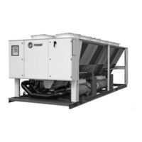
Trane R Series Installation, Operation And Maintenance Manual (170 pages)
Air-Cooled Helical Rotary Liquid Chillers
Brand:
Trane
| Category:
Chiller
| Size: 9.4 MB
Table of Contents
Warnings, Cautions and Notices
2
Table of Contents
4
Model Number Description
8
Outdoor Unit Nameplate
8
Compressor Nameplate
8
Unit Model Number
9
Compressor Model Number
10
Compressor Serial Number
10
General Data
11
Unit Description
11
Accessory/Option Information
11
Isolator Shipping Location
11
Pre-Installation
22
Unit Inspection
22
Inspection Checklist
22
Storage
22
Installation Responsibilities
22
General
22
Dimensions and Weights
23
Clearances
23
Dimensions
26
Weights
38
Installation - Mechanical
41
Location Requirements
41
Noise Considerations
41
Foundation
41
Clearances
41
Rigging
41
Lifting Procedure
41
Isolation and Sound Emission
44
Unit Isolation and Leveling
44
Drainage
48
Evaporator Water Piping
48
Evaporator Piping
48
Entering Chilled Water Piping
49
Leaving Chilled Water Piping
49
Evaporator Drain
49
Evaporator Flow Switch
49
Water Pressure Gauges
52
Water Pressure Relief Valves
52
Freeze Protection
52
Low Evaporator Refrigerant Cutout, Glycol Recommendations
53
Procedure
53
Specials
53
Installation - Mechanical - Remote Evaporator Option
55
System Configuration and Interconnecting Refrigerant Piping
55
Line Sizing
59
Liquid Line Sizing Steps
59
Suction Line Sizing Steps
60
Suction Accumulator Sizing
60
Piping Installation Procedures
61
Refrigerant Sensors
61
Refrigerant Pressure Relief Valve Venting
61
Leak Test and Evacuation
62
Refrigerant and Additional Oil Charge
63
Refrigerant Charge Determination
63
Oil Charge Determination
63
Installation - Electrical
64
General Recommendations
64
Installer-Supplied Components
85
Power Supply Wiring
85
Control Power Supply
86
Heater Power Supply and Convenience Outlet (Packaged Units Only)
86
Interconnecting Wiring
87
Chilled Water Pump Control
87
Alarm and Status Relay Outputs (Programmable Relays)
88
Relay Assignments Using Techview
88
Low Voltage Wiring
88
Emergency Stop
89
External Auto/Stop
89
External Circuit Lockout - Circuit #1 and #2
89
Ice Building Option
89
External Chilled Water Setpoint (ECWS) Option
89
External Current Limit Setpoint (ECLS) Option
90
Chilled Water Reset (CWR)
90
Communications Interface Options
91
Optional Tracer Communications Interface
91
Lontalk Communications Interface for Chillers (LCI-C)
91
Bacnet Communications Interface (BCI-C)
92
Object and Diagnostic Data Points with Corresponding Chiller Models
98
BCI-C Alarming
105
Operating Principles
106
Refrigeration Cycle
106
Refrigerant R-134A
106
Compressor
106
Condenser and Subcooler
107
Expansion Valve
108
Evaporator
108
Oil System
108
Controls Interface
109
Overview
109
Dynaview Display
109
Key Functions
109
Display Screens
110
Modes Screen
111
Chiller Screen
115
Compressor Screen
115
Refrigerant Screen
115
Setpoint Screen
116
Diagnostic Screen
117
Power-Up
117
Display Formats
117
Units
117
Languages
117
Techview
117
Software Download
118
Unit View
118
Compressor Service View
119
Status View
119
Setpoint View
119
Diagnostics View
120
Configuration View
120
Software View
123
Binding View
123
Replacing or Adding Devices
123
Pre-Start Checkout
126
Installation Checklist
126
Receiving
126
Unit Location and Mounting
126
Unit Piping
126
Electrical Wiring
126
General
127
Unit Voltage Power Supply
128
Unit Voltage Imbalance
128
Unit Voltage Phasing
128
Water System Flow Rates
129
Water System Pressure Drop
129
CH530 Set-Up
129
Unit Start-Up Procedures
130
Daily Unit Start-Up
130
General
130
Seasonal Unit Start-Up Procedure
130
System Restart after Extended Shutdown
131
Shutdown
136
Temporary Shutdown and Restart
136
Extended Shutdown Procedure
136
Maintenance
137
Weekly Maintenance
137
Monthly Maintenance
137
Annual Maintenance
137
Refrigerant and Oil Charge Management
140
R-134A Field Charging Procedure
141
Factory Refrigerant Charging Procedure (Initial)
141
Field Refrigerant Charging Procedure
141
Adding Charge
141
Charge Isolation in the High or Low Side of System
142
High Side Charge Isolation Procedure
142
Low Side Charge Isolation Procedure
142
Refrigerant Filter Replacement Procedure
143
Lubrication System
143
Oil Charging Procedure
143
Factory (Initial) Oil Charging Procedure
145
Field Oil Charging Procedure
145
Evaporator Tube Replacement
146
Compressor Replacement
146
Condenser Maintenance
147
Condenser Coil Cleaning
147
Travel Restraint
147
Diagnostics
148
Legend to Diagnostics Table
148
Starter Diagnostics
148
Main Processor Diagnostics
154
Communication Diagnostics
162
Main Processor Boot Messages and Diagnostics
167
Unit Wiring
168
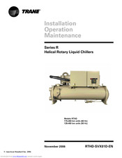
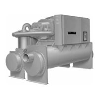
Trane R Series Installation Operation & Maintenance (184 pages)
Helical Rotary Liquid Chillers. 175-450 ton units (60 Hz) 125-450 ton units (50 Hz)
Brand:
Trane
| Category:
Chiller
| Size: 5.36 MB
Table of Contents
Table of Contents
3
General Information
5
Literature Change History
5
Unit Identification - Nameplates
5
Unit Inspection
6
Inspection Checklist
6
Loose Parts Inventory
6
Unit Description
6
Model Number Coding System
7
Unit Model Number
7
Installation Overview
12
Installation Mechanical
19
Storage
19
Location Requirements
19
Moving and Rigging
21
Lifting Procedure
25
Isolation Pads
29
Unit Leveling
30
Water Piping
31
Water Pressure Drop Data
39
Condenser Water Regulating Valve
49
Water Treatment
50
Water Pressure Gauges and Thermometers
51
Water Pressure Relief Valves
51
Flow Sensing Devices
51
Refrigerant Pressure Relief Valve Venting
52
Thermal Insulation
54
Installation Electrical
57
General Recommendations
57
Power Supply Wiring
57
Compressor Motor Phase Sequencing
59
Correcting Improper Electrical Phase Sequence
60
Application of Solid-State Starters
64
Module Connections for Interconnecting Wiring
67
Interconnecting Wiring (Field Wiring Required)
67
Operating Principles Mechanical
75
General
75
Refrigeration (Cooling) Cycle
75
Compressor Description
78
Oil Management System
80
Oil Cooler
83
Operator Interface Controls
85
CH530 Communications Overview
85
Controls Interface
85
Dynaview Interface
86
Display Screens
87
Keypad/Display Lockout Feature
88
Main Screen
89
Reports Screen
94
Settings Screen
96
Diagnostic Screen
98
Techview
99
Minimum PC Requirements to Install and Operate Techview
100
Unit View
101
Status View
102
Setpoint View
105
Manual Override View
109
Diagnostics View
111
Software View
115
Binding View
116
Software Download
117
Unit Start-Up
119
Power up
119
Power up to Starting
119
Stopped to Starting
121
Seasonal Unit Start-Up Procedure
123
Unit Shutdown
127
Normal Shutdown to Stopped
127
Seasonal Unit Shutdown
128
Periodic Maintenance
129
Overview
129
Weekly Maintenance and Checks
129
Monthly Maintenance and Checks
129
Annual Maintenance
130
Scheduling Other Maintenance
131
Maintenance Procedures
135
Cleaning the Condenser
135
Mechanical Cleaning Procedure
135
Chemical Cleaning Procedure
138
Cleaning the Evaporato
139
Compressor Oil
139
Oil Sump Level Check
139
Removing Compressor Oil
141
Oil Charging Procedure
141
Replacing the Main Oil Filt E (Hot Filter)
142
Replacing the Gas Pump Oil Filter
143
Refrigerant Charge
143
Refrigerant Charging
144
Diagnostics
147
Wiring Schematics
161
Unit Electrical Data
161
Advertisement
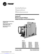
Trane R Series Installation Operation & Maintenance (188 pages)
R Series Rotary Liquid Chillers Water-Cooled and Condenserless
Brand:
Trane
| Category:
Chiller
| Size: 8.68 MB
Table of Contents
Table of Contents
3
General Information
5
Unit Identification
5
Unit Inspection
5
Inspection Checklist
5
Loose Parts Inventory
5
Unit Description
5
Installation Responsibilities
9
Nameplates
10
Unit Nameplate
10
Model Number Coding System
11
Storage
14
Installation - Mechanical
15
Pre-Installation
15
Location Requirements
15
Rigging
15
Lifting Procedure
16
Unit Isolation and Leveling
27
Water Piping
31
Evaporator Water Piping (for RTWA and RTUA Units Only)
31
Leaving Chilled Water Piping
33
Condenser Water Piping (for RTWA Units Only)
38
Water Regulations Valve (for RTWA Units Only)
39
Water Treatment
41
Water Pressure Gauges
41
Water Pressure Relief Valves
41
Field-Installed Water Temperature Sensors
41
Water Sensor Installation Procedure
41
Refrigerant Relief Valve Venting
42
Initial Leak Test
44
Installation - Remote Condenser
45
Remote Air-Cooled Condenser Interconnecting Refrigerant Piping
45
Installation - Electrical
58
Installer-Supplied Components
62
Power Supply Wiring
62
Interconnecting Wiring
62
Rtwa
66
Air-Cooled Condenser RTCA
66
Low Voltage Wiring
67
Optional Bidirectional Communications Link (BCL)
75
Remote Clear Language Display Installation Procedure
77
Installation Checklist
81
Operating Principles
83
Refrigeration (Cooling) Cycle
85
Oil System Operation (RTWA and RTUA Only)
87
Controls Interface
91
Clear Language Display Keypad Overview
91
Diagnostics
112
Operational Features
113
DIP Switch Settings
120
Pre-Start Checkout
122
Unit Voltage Power Supply
123
Unit Voltage Imbalance
124
Unit Voltage Phasing
124
Water System Flow Rates
126
Water System Pressure Drop
126
Start-Up Procedures
127
System Superheat
128
System Subcooling
128
Unit Shutdown Procedures
131
Temporary Shutdown and Restart
131
Extended Shutdown Procedure
131
System Restart after Extended Shutdown
131
Periodic Maintenance
133
Weekly Maintenance
133
Monthly Maintenance
133
Annual Maintenance
133
Maintenance
137
Cleaning the Evaporator (RTWA and RTUA)
137
Cleaning the Condenser
137
Water Treatment
139
Oil Separator Level Check
139
Refrigerant Charging
143
Adding Refrigerant
143
Low Side Repairs
144
High Side Repair
144
Diagnostics
146
Unit Wiring
155
American Standard
188
Trane R Series Installation Operation & Maintenance (84 pages)
R Series Air-Cooled Helical Rotary Liquid Chiller
Brand:
Trane
| Category:
Chiller
| Size: 3.07 MB
Table of Contents
General Information
2
External Circuit Lockout - Circuit 1 and Circuit
2
Table of Contents
4
Unit Inspection
7
Loose Parts Inventory
7
General Data - Standard Cooling Unit
8
General Data - Free-Cooling Unit
16
General Data - Heat Recovery Unit
18
Unit Dimensions
23
Installation - Mechanical
24
Installation Responsibilities
24
Nameplates
24
Storage
26
Location Requirements
26
Isolation and Sound Emission
26
Neoprene Isolator Installation
26
Noise Considerations
26
Foundation
27
Clearances
27
Drainage
28
Unit Water Piping
28
Unit Piping
28
Entering Chilled Water Piping
29
Leaving Chilled Water Piping
29
Heat Recovery Water Piping
29
Evaporator Drain
29
Evaporator Flow Switch
29
Water Treatment
30
Water Pressure Gauges
41
Water Pressure Relief Valves
41
Freeze Protection
41
Installation - Electrical
42
General Recommendations
43
Installer-Supplied Components
48
Power Supply Wiring
48
Control Power Supply
48
Heater Power Supply
48
Water Pump Power Supply
48
Interconnecting Wiring
49
Chilled Water Flow (Pump) Interlock
49
Chilled Water Pump Control
49
Alarm and Status Relay Outputs
52
(Programmable Relays)
52
Low Voltage Wiring
54
External Emergency Stop
54
External Auto/Stop
54
Ice Making Option
55
External Chilled Water Setpoint (CWS)
55
External Current Limit Setpoint (CLS)
56
Outdoor Air Temperature Sensor
56
Communication Card CSR
57
Communication Link Connection Procedure
57
Lontalk Communication Interface
58
Operating Principles
64
System Schematics
64
Pre-Start Checkout
67
Installation Checklist
67
Receiving
67
Unit Location and Mounting
67
Unit Piping
67
Electrical Wiring
67
General
68
Unit Voltage Power Supply
69
Unit Voltage Imbalance
69
Unit Voltage Phasing
69
Water System Flow Rates
70
Water System Pressure Drop
70
Unit Start-Up Procedures
71
Daily Unit Start-Up
71
General
72
Seasonal Unit Start-Up Procedure
73
System Restart after Extended Shutdown
73
Unit Shutdown Procedures
74
Temporary Shutdown and Restart
74
Extended Shutdown Procedure
74
Maintenance
75
General
75
Weekly Maintenance
75
Monthly Maintenance
75
Annual Maintenance
75
Maintenance Procedures
76
Refrigerant Emission Control
76
Refrigerant and Oil Charge Management
77
R134A Field Charging Procedure
77
Refrigerant Charging
77
Isolating the Refrigerant in the High Pressure Side
78
Isolating the Refrigerant in the Low Pressure Side
78
Adding Refrigerant
79
Refrigerant Filter Changing Procedure
79
Lubrication System
80
Oil Charging Procedure
80
Factory (Initial) Oil Charging Procedure
81
Field Oil Charging Procedure
82
Evaporator Heat Tape Checkout Procedure
83
Safety Recommendations
83
Trane R Series Installation Operation & Maintenance (138 pages)
Air-Cooled Helical Rotary Liquid Chillers
Brand:
Trane
| Category:
Chiller
| Size: 12.32 MB
Table of Contents
Table of Contents
2
I-Model Number
3
II-General Information
4
III-Installation Mechanical
19
IV-Installation Electrical
33
V-Operating Principles
55
VI-Controls Interface
61
VII-Diagnostics
82
VIII-Pre-Start Checkout
93
IX-Unit Start-Up Procedures
97
X-Periodic Maintenance
100
XI-Maintenance Procedures
105
XII-Wiring Diagram
113
XIII-Standard Conversion Table
137
Trane R Series Installation Operation & Maintenance (76 pages)
Air-Cooled Helical-Rotary Liquid Chiller 50 Hz 400-1500 kW
Brand:
Trane
| Category:
Chiller
| Size: 3.79 MB
Table of Contents
Table of Contents
2
General Information
6
Unit Inspection
6
Loose Parts Inventory
6
General Data Tables
7
Installation - Mechanical
19
Installation Responsibilities
19
Storage
19
Special Lifting and Moving Instructions
20
Isolation and Sound Emission
21
Foundation
22
Clearances
22
Dimensional Data
23
Unit Isolation and Leveling
30
Neoprene Isolator Installation
30
Drainage
30
Evaporator Grooved Pipe
30
Water Treatment
31
Entering Chilled-Water Piping
31
Leaving Chilled-Water Piping
31
Evaporator Drain
31
Evaporator Flow Proving Device
31
Performance Data
32
Water Pressure Gauges
34
Water Pressure Relief Valves
35
Freeze Protection
35
Refrigerant Cutouts and Glycol Percentages
36
Installation - Electrical
39
General Recommendations
39
Wire Sizing
40
Electrical Data Tables
42
Installer-Supplied Components
46
Power Supply Wiring
46
Control Power Supply
46
Heater Power Supply
46
Water Pump Power Supply
47
Interconnecting Wiring
47
Alarm and Status Relay Outputs (Programmable Relays)
48
Relay Assignments Using Techview
49
Low Voltage Wiring
49
Emergency Stop
49
External Auto/Stop
49
External Circuit Lockout
50
Ice-Building Option
50
Optional External Chilled-Water Set Point (ECWS)
51
Optional Current Limit Setpoint
51
Optional Tracer Comm 3 Interface
53
Lontalk® Communications Interface for Chillers (LCI-C)
54
Operating Principles
55
Pre-Start Checkout
57
Installation Checklist
57
General
58
Unit Voltage Power Supply
58
Unit Voltage Imbalance
59
Unit Voltage Phasing
59
Water System Flow Rates
59
Water System Pressure Drop
59
CH.530 Set-Up
59
Unit Startup Procedures
60
Daily Unit Startup
60
General
60
Seasonal Unit Startup Procedure
61
System Restart after Extended Shutdown
61
Unit Shutdown Procedures
62
Temporary Shutdown and Restart
62
Extended Shutdown Procedure
62
Periodic Maintenance
63
Maintenance Procedures
64
Refrigerant Emission Control
64
Refrigerant and Oil Charge Management
64
Charge Isolation in the High or Low Side of System
66
Filter Replacement Procedure
68
Lubrication System
68
Prelubrication
70
Field Oil Charging Procedure
71
Trane R Series Diagnostic Troubleshooting Repair (88 pages)
70-125 Ton Air-Cooled and Water-Cooled Rotary Liquid Chillers
Brand:
Trane
| Category:
Chiller
| Size: 1.84 MB
Table of Contents
Table of Contents
3
General Information
4
Service Philosophy
4
System Description
5
System Level Components
5
Interprocessor Communications
8
IPC Diagnostics
8
Troubleshooting Modules Using IPC Diagnostics
9
Troubleshooting Procedure
12
Temperature Sensor Checkout
15
Temperature Sensor Checkout Procedure
15
Compressor Operation
19
Restart Inhibit Timer
19
Compressor Start/Stop
20
Variable Speed Inverter/Condenser Fan Control
21
Outdoor Air Temperature and Fan Control
22
VSF Inverter Fault
22
Current Transformer
23
CT and MCSP Compressor Current Input Checkout Procedure
24
Under-Over Voltage Transformer
32
Under-Over Voltage Transformer Checkout
32
Compressor Capacity
34
Checkout Procedure for MCSP Load/Unload Outputs
35
Checkout Procedure for the Slide Valve and Load
36
Unload Solenoids
36
Checkout Procedure for MCSP Step Load Output
39
Checkout Procedure for Step Load Solenoid Valve
40
And Piston
40
Module Power and Miscellaneous I/O
41
Power Supply
41
Clear Language Display (CLD) 1U6 Keypad Overview
42
Chiller Module (CPM) (1U1)
46
Options Module (CSR) (1U2)
50
Electronic Expansion Valve Module (EXV) (1U3)
58
Compressor Module (MCSP) (1U4 and 1U5)
72
Interprocessor Communication Bridge Module (IPCB) (1U7)
78
Lontalk® Communications Interface - Chillers Module
79
(Lci-C) (1U8)
79
Variable Speed Fan System
80
Inverter Diagnostics
80
Troubleshooting Procedure
82
Other Service Features
85
Service Pumpdown
85
Circuit Lockout
87
Circuit Diagnostic Reset
87
Advertisement
Related Products
Trane RSCA0200F0-F1
Trane RSXA0200F1
Trane RTAA-125
Trane RTAD 165 SE
Trane RAUP600D
Trane RAUP400K
Trane RAUP5003
Trane RuptureGuard CVHS
Trane Sintesis RTAF 175 SE SN LN
Trane Sintesis RTAF 145 SE SN LN
Trane Categories
Air Conditioner
Heat Pump
Chiller
Air Handlers
Furnace
More Trane Manuals
Login
Sign In
OR
Sign in with Facebook
Sign in with Google
Upload manual
Upload from disk
Upload from URL