Sign In
Upload
Manuals
Brands
Trane Manuals
Heat Pump
Axiom GEVE006
Trane Axiom GEVE006 Manuals
Manuals and User Guides for Trane Axiom GEVE006. We have
1
Trane Axiom GEVE006 manual available for free PDF download: Installation And Maintenance Manual
Trane Axiom GEVE006 Installation And Maintenance Manual (119 pages)
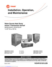
Water Source Heat Pump, Axiom Horizontal/Vertical, ½–25 Tons, 60 Hz
Brand:
Trane
| Category:
Heat Pump
| Size: 7.81 MB
Table of Contents
Warnings, Cautions and Notices
2
Environmental Concerns
2
Responsible Refrigerant Practices
2
Equipment Damage from Ultraviolet (UV) Lights
2
Table of Contents
3
Model Number Descriptions: 1/2–25 Ton (GEH/GEV)
4
Gev)
5
Model Number Descriptions: 1,5-6 Ton (EXH/ EXV)
5
Exv)
6
Overview of Manual
6
Unit Nameplate
6
Compressor Nameplate
6
Model Number Description
6
General Information
7
Controls
7
System Input Devices and Functions
7
High/Low Pressure Switch
7
Pump Module (Field Installed Accessory)
8
Waterside Economizer
8
Boilerless Control/Electric Heat
8
Supplemental or Boilerless Electric Heat/Hot Gas Reheat
8
Refrigerant Charge Table
9
Pre-Installation
10
Unit Inspection Checklist
10
Jobsite Inspection Checklist
10
Jobsite Storage
10
Unit Dimensions and Weights
11
GEH and EXH Clearance Dimensions
11
GEH 1/2–5 Tons and EXH 1,5–6 Tons Clearance
11
GEH 6-15 Tons Clearance
11
GEV 0,5-5 Tons and EXV 1,5-6 Tons Clearance Dimensions
12
GEV 6–10 Tons Clearance Dimensions
12
GEV 1,5–25 Tons Clearance Dimensions
12
Left Return/Left Supply (GEH/EXH) Diagram
13
Left Return/Left Supply (GEH/EXH) Table
13
Left Return/Back Supply (GEH/EXH)
14
Left Return/Right Supply (GEH/EXH)
15
Right Return/Left Supply (GEH/EXH)
16
Right Return/Back Supply (GEH/EXH)
17
Right Return/Right Supply (GEH/EXH)
18
Left Return/Top Supply
19
Left Return/Back Supply
20
Right Return/Top Supply
21
Right Return/Back Supply
22
Left Return/Right Supply
25
GEH 6-10 Tons 60 Hz; GEH 6-7,5 Tons 50 Hz—Left Return/Back Supply
26
GEH 12,5-15 T 60 Hz/Geh 10-12,5 T 50 Hz—Right Return/Left Supply
27
GEH 12,5-15 T 60 Hz; GEH 10-12,5 T 50 Hz—Right Return/Back Supply
28
GEH 12,5-15 T 60 Hz; GEH 10-12,5 T 50 Hz — Left Return/Right Supply
29
GEH 12,5-15 T 60 Hz; GEH 10-12,5 T 50 Hz—Left Return/Back Supply
30
GEV 6-10 T 60 Hz; 6 and 7,5 T 50 Hz—Front Return/Back Supply
31
GEV 6–10 T 60 Hz; 6 and 7,5 T 50 Hz—Front Return/Top Supply
32
GEV 6–10 T 60 Hz; 6 and 7,5 Ton 50 Hz—Back Return/Front Supply
33
GEV 6–10 T 60 Hz; 6 and 7,5 T 50 Hz — Back Return/Top Supply
34
GEV 12,5–15T 60 Hz; GEV 10 and 12,5T 50 Hz-Front Return/Back Supply
35
GEV 12,5–15T 60 Hz;Gev 10 and 12,5T 50 Hz—Back Return/Front Supply
36
GEV 12,5–15T 60 Hz; GEV 10 and 12,5T 50 Hz—Front Return/Top Supply
37
GEV 12,5–15T 60 Hz; GEV 10 and 12,5T 50 Hz—Back Return/Top Supply
38
GEV 20 and 25T 60 Hz; GEV 15 and 20T 50 Hz—Front Return/Back Supply
39
GEV 20 and 25T 60 Hz; GEV 15 and 20T 50 Hz - Back Return/Front Supply
40
GEV 20 and 25 T 60 Hz; GEV 15 and 20 T 50 Hz—Front Return/Top Supply
41
GEV 20 and 25 T 60 Hz; GEV 15 and 20 T 50 Hz—Back Return/Top Supply
42
GEH and EXH Waterside Economizer
43
GEH and EXH Hanging Unit Waterside Economizer
44
GEH6-10T 60Hz, Right Return/Geh6-7,5T 50Hz, R Return/Waterside Econom
45
GEH 6-10T 60Hz, L Return/Geh 6-7,5 T50 Hz, L Return, Waterside Econom
46
GEH 12,5-15T 60Hz, R Return/Geh 10-12,5T 50Hz, R Return, Waterside
47
GEH 12,5-15T 60 Hz, L Return/Geh 10-12,5T 50 Hz, L Return, Waterside
48
GEV 6-10 T 60 Hz; 6 and 7,5 Ton 50 Hz, Waterside Economizer
49
GEV 12,5-25 Tons (150-300), Waterside Economizer
50
Unit Weights GEH006-060 (60 Hz)
50
Unit Weights GEV006-060 (60 Hz)
50
Unit Weights
51
Weight Distribution for Hanging the GEH and EXH Model
51
Weight Distribution 0,5-5 Ton and EXH070
51
Weight Distribution GEH 6-15 Ton
51
Main Electrical
52
Electric Heat Requirements/Low Voltage Wiring (AC) Requirements
52
Filter Installation
52
General Installation Checks
52
Supply-Air Ductwork
53
Return-Air Ductwork
53
Ducted Panel
53
Opening Size and Part Number GEH
53
Ducted Filter Rack
54
Dual Filtration (GEH 0,5-5 Ton and EXH 1,5-6 Ton)
54
Opening Size and Part Number EXH
54
Ducted Filter Opening Size
54
Return-Air Duct Panel
55
Sound Attenuation Pad
55
Hanging the Horizontal Unit
55
Condensate Drain Connection
56
Supply/Return Pipe Connections
56
Types of Hose Connections
56
Flexible Hoses/Deluxe Ball Valve Hose Kit
56
Manual Balance Hose Kit
57
Automatic Balance Hose Kit
57
Cleaning and Flushing the Water Loop
57
Field Installed Power Wiring
57
Main Unit Power Wiring
58
Control Power Transformer
58
Thermostat Location
58
Controls Using 24 VAC
58
Blower Motor Speed-Tap Retrofit
59
Low-Voltage Connection (GEH/V 0,5-5 T and EXH/V 1,5-6 T Equipment)
59
Low-Voltage Connection (GEH/V 6-25 Ton)
59
Service Access Panel
59
Hole Plug Installation
60
Removing Speed-Tap Wire
60
Connecting Desired Speed-Tap Wire
60
Relay Location
60
Air Flow Adjustment
61
Fan Motor and Sheave Adjustment
61
ECM Control Board and Dip Switch Setting
61
Waterside Economizer Installation
62
Economizer Part Numbers
64
Waterside Economizer Installation for GEH and GEV 6 - 25 Ton Models
65
Actuator/Factory Harness Wire Table
65
Economizer Start-Up Sequence
66
Waterside Economizing Three-Way Valve Specifications
67
Electrical Data: Standard Static Motors, 0,5–5 Tons
68
Electrical Data - High Static Motors - 0,5-5 Tons
72
Electrical Data - ECM Motors - 1,5-6 Tons
76
Pre-Start Checklist
78
Initial Unit Start-Up
79
Start-Up Checklist and Log
79
Operating Pressures
79
Operating Pressures in Cooling/Heating for GE Units
80
Operating Pressures in Cooling/Heating for EX Units
93
Water Pressure Drop
99
Cooling Water Pressure Drops (WPD) in Feet of Head for GE Units
99
Cooling Water Pressure Drops (WPD) in Feet of Head for EX Units
99
Heating Water Pressure Drops (WPD) in Feet of Head for GE Units
99
Water Volume
100
Heating Water Pressure Drops (WPD) in Feet of Head for EX Units
100
Water Volume for GE Units
100
Water Volume for EX Units
100
Condensate Trap
101
Filter Sizing
101
Water Quality
101
Preventive Maintenance
101
Troubleshooting
102
Deluxe Controls
102
Diagnostic Leds
102
Troubleshooting Table
103
Wiring Diagrams
104
Basic-208V - 60 Hz - 1 Ph Diagram
104
Isolation Valve Wiring
104
Basic 24V - 460V-60 Hz - 3 Ph
105
EXH/EXV - (ECM Motor Wiring Diagram)
106
Deluxe-380-420V - 50 Hz - 3 Ph Diagram
107
Deluxe 24V - 460V-60 Hz - 3 Ph Diagram
108
Tracer ZN510 460V-60 Hz - 3 Ph Diagram
111
Tracer ZN524-460V - 60 Hz - 1 Ph Diagram
113
Tracer ZN524 460V-60 Hz - 3 Ph Diagram
114
Warranty Information
116
Standard Warranty
116
Extended Warranty
116
Advertisement
Advertisement
Related Products
Trane GEVE 006-060
Trane Axiom GEVE009
Trane Axiom GEVE012
Trane Axiom GEVE015
Trane Axiom GEVE030
Trane Axiom GEVE036
Trane Axiom GEVE042
Trane Axiom GEVE048
Trane Axiom GEVE060
Trane Axiom GEVE090
Trane Categories
Air Conditioner
Heat Pump
Chiller
Air Handlers
Furnace
More Trane Manuals
Login
Sign In
OR
Sign in with Facebook
Sign in with Google
Upload manual
Upload from disk
Upload from URL