Sign In
Upload
Manuals
Brands
Toyota Manuals
Automobile
2006 Tundra
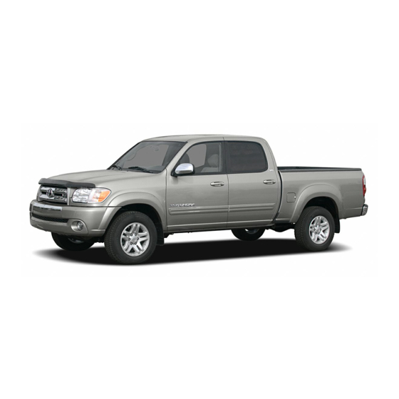
Toyota 2006 Tundra Manuals
Manuals and User Guides for Toyota 2006 Tundra. We have
3
Toyota 2006 Tundra manuals available for free PDF download: Service - Repair - Maintenance, Owner's Manual, Pocket Reference Manual
Toyota 2006 Tundra Service - Repair - Maintenance (4947 pages)
Brand:
Toyota
| Category:
Automobile
| Size: 81.09 MB
Table of Contents
General Information
4
Precaution
4
Preparation
4
Repair Procedures
4
Check Piston Stroke of Overdrive Brake
5
References
5
Specifications
5
Cautions, Notices, Hints
5
Identification Information
6
Vehicle Identification and Engine Serial Number
6
Repair Instructions
7
Basic Repair Hint
7
Precoated Parts
7
Installation and Removal of Battery Terminal
7
Medium Current Fuse and High Current Fuse Equal Amperage Rating
8
Vehicle Lift and Support Locations
11
For All of Vehicles
12
General Notice
12
Steering Wheel Pad
14
Front Passenger Airbag Assembly
15
Seat Belt Pretensioner
16
Side Airbag Assembly
17
Curtain Shield Airbag Assembly
18
Never Disassemble the Curtain Shield Airbag Assembly
18
Airbag Sensor Assembly
19
Wire Harness and Connector
19
For Vehicles Equipped with a Catalytic Converter
20
If Vehicle Is Equipped with Mobile Communication System
20
For Using Obd II Scan Tool or Hand−Held Tester
20
How to Troubleshoot Ecu Controlled Systems
21
Table of Contents
21
How to Proceed with Troubleshooting
22
Customer Problem Analysis
23
Customer Problem Analysis Check
23
Tire Pressure Warning System
24
Diagnostic Trouble Code Check Procedure
25
Diagnostic Trouble Code Check
26
Symptom Simulation
27
When Vibration Seems to be the Major Cause
27
When the Problem Seems to Occur When the Suspect Area Is Heated
28
Water Sprinkling Method
28
When a Malfunction Seems to Occur When Electrical Load Is Excessive
28
Diagnostic Trouble Code Chart
29
Problem Symptoms Table
30
Circuit Inspection
31
How to Use the Diagnostic Chart and Inspection
33
Connector Connection and Terminal Inspection
33
Open Circuit
33
Short Circuit
33
Connector Handling
34
Continuity Check (Open Circuit Check)
34
Resistance Check (Short Circuit Check)
34
Visual Check and Contact Pressure Check
34
Check Open Circuit
35
Check the Continuity
35
Check Short Circuit
36
Check the Resistance with Ground
36
Check and Replace Ecu
37
Terms
38
Abbreviations Used in this Manual
38
Anti−Lock Brake System
38
Supplemental Restraint System
41
Outside Vehicle
46
General Maintenance
46
General Notes
46
Tires
46
Inside Vehicle
47
Lamps
47
Horn
47
Windshield Wiper and Washer
47
Accelerator Pedal
48
Clutch Pedal
48
Brake Pedal
48
Brakes
48
Under Hood
49
Windshield Washer Fluid
49
Brake and Clutch Fluid Levels
49
Engine Drive Belts
49
Engine Inspection
50
Inspect Air Filter
50
Inspect Exhaust Pipes and Mountings
50
Replace Air Filter
50
Brake Inspection
52
Inspect Brake Line Pipes and Hoses
52
Inspect Front Brake Pads and Discs
52
Inspect Rear Brake Linings and Drums
52
Chassis Inspection
53
Inspect Steering Linkage
53
Inspect Steering Gear Housing Oil
53
Inspect Ball Joints and Dust Covers
53
Lubricate Propeller Shaft and Tighten Bolts
54
Body
55
Tighten Bolts and Nuts on Chassis and Body
55
Maintenance Equipment
56
Engine Mechanical (1Gr−Fe)
57
SST (Special Service Tools)
57
Recommended Tools
60
SSM (Special Service Materials)
62
Engine Mechanical (2Uz−Fe)
63
Transfer
124
Suspension and Axle
133
Brake
145
Steering
149
Supplemental Restraint System
157
Body Electrical
160
Air Conditioning
168
Standard Bolt
173
How to Determine Bolt Strength
173
Specified Torque for Standard Bolts
174
How to Determine Nut Strength
175
Location
272
System Diagram
273
To A/F Relay
274
To EFI Relay
274
To EFI No.2 Fuse
274
Check for Intermittent Problems
278
Basic Inspection
279
Is Battery Voltage 11 V or more When Engine Stopped?
279
Is Engine Cranked?
279
Does Engine Start?
279
Check Air Filter
280
Check Idle Speed
280
Check Fuel Pressure
280
Check for Spark
280
Registration
281
Input Instructions
281
Hand−Held Tester
281
Cursor Operation
281
READ VIN (Vehicle Identification Number)
282
Write Vin
283
List of Disable a Monitor
285
Checking Monitor Status
293
Procedure (Using Hand−Held Tester)
293
Readiness Monitor Drive Pattern
294
Purpose of the Readiness Tests
294
Catalyst Monitor (Active Air−Fuel Ratio Control Type)
295
Drive Pattern
295
Monitor Status
295
Evap Monitor (Vacuum Pressure Monitor)
296
Air−Fuel Ratio (A/F) and Oxygen Sensor (Ho2) Monitor
298
Oxygen Sensor Heater Monitor
299
Dtc Check / Clear
309
Check Dtc
309
Clear Dtc
309
Check Mode Procedure
310
Fail−Safe Chart
312
Data List
314
Active Test
322
System Check
323
Monitor Description
393
Fail Safe
393
Monitor Strategy
393
Typical Enabling Conditions
394
Typical Malfunction Thresholds
394
Component Operating Range
394
Wiring Diagram
395
Inspection Procedure
395
Throttle Position Expressed as Percentage and Voltage
396
Check Voltage between Terminals VC and E2 of ECM Connector
398
Check Voltage between Terminal FPR and E1 of ECM
444
Check Fuel Pump Relay
444
Check Spark Plug and Spark of Misfiring Cylinder
454
Change Normal Spark Plug and Check Spark of Misfiring Cylinder
455
Check ECM Terminal of Misfiring Cylinder
458
Circuit Description
484
Measure Resistance between Terminal PPMP of ECM and Body Ground
515
Measure Voltage and Resistance of Pump Module Connector
517
Evaporative Emission Control System Leak Detected (Gross Leak)
519
Evaporative Emission Control System Leak Detected (very Small Leak)
519
Vehicle Speed Sensor ”A”
524
Vehicle Speed Sensor ”A” Intermittent/Erratic/High
524
Check Voltage between Terminal SPD and E1 of ECM Connector
527
Brake Switch ”A”/”B” Correlation
528
Idle Air Control System
533
Cold Start Idle Air Control System Performance
537
Cold Start Ignition Timing Performance
537
Check EFI No. 1 Fuse of Engine Room J/B
545
Starter Relay Circuit High
549
VIN Not Programmed or Mismatch ECM/PCM
554
Throttle Actuator Control Motor Circuit Low
556
Throttle Actuator Control Motor Circuit High
556
Throttle Actuator Control System−Stuck Open
560
Throttle Actuator Control System−Stuck Closed
560
Check Throttle Control Motor
563
Throttle Actuator Control Motor Current Range/Performance
564
Throttle Actuator Control Throttle Body Range/Performance
569
Confirmation Driving Pattern
593
Read Value Output Voltage of A/F Sensor
597
Check Resistance of Air−Fuel Ratio (A/F) Sensor Heater
600
Check A/F Relay
600
Evaporate Emission System Switching Valve Control Circuit Low
620
Evaporate Emission System Switching Valve Control Circuit High
620
Evaporate Emission System Reference Orifice Clog up
628
Evaporate Emission System Reference Orifice High Flow
628
Operation A: Atmospheric Pressure Measurement
630
Operation B: 0.02 Inch Leak Pressure Measurement
630
Operation D: Purge VSV Monitor
630
Operation C: EVAP Leak Check
630
A/F Sensor Circuit Slow Response (Bank 1 Sensor 1)
634
A/F Sensor Circuit Slow Response (Bank 2 Sensor 1)
634
Perform EVAP System Manual Operation Check
651
Perform EVAP System Step 1/5 Check
652
Perform Active Test of Purge VSV
660
Check Fuel Tank Cap
661
Inspect EVAP VSV
662
Perform Active Test for Vent Valve
665
Inspect Pump Module Power Source Circuit
666
Inspect Vent Valve Operation of Pump Module
667
Connect the EVAP Pressure Tester Tool to the Canister with the Adapter
671
Key−Off Monitor Confirmation
673
Monitor Conditions
673
Purge Flow Monitor Confirmation (P0441)
673
IACV Control VSV Circuit
676
Connect Hand−Held Tester and Check Operation of VSV for ACIS
677
Cranking Holding Function Control Circuit
679
Check Operation of Engine Cranking
679
Connect Hand−Held Tester, and Check STA Signal
680
Check Park/Neutral Position Switch Assembly
681
Check Starter Relay
681
ECM Power Source Circuit
684
Check Voltage between Terminals +B and E1 of ECM Connector
685
Check IGN Fuse
686
Check Ignition Switch
686
Check Voltage between Terminal MREL of ECM Connector and Body Ground
686
Check EFI Relay)
687
Fuel Pump Control Circuit
689
Check Fuel Pump Operation
689
Connect Hand−Held Tester, and Check Operation of Fuel Pump Relay
689
Check Fuel Pump
690
Check Circuit Opening Relay
690
Check Voltage between Terminal FC and E1 of ECM Connector
691
Check Fuel Pump Resistor
691
MIL Circuit
692
Check Harness and Connector
693
Check that MIL Lights up
694
Inspect Combination Meter Assy (MIL Circuit)
694
O2S Test Result
716
Fuel Injector
728
Camshaft Position ”A” Actuator Circuit
765
Oxygen Sensor Heater Control Circuit Low
785
Oxygen Sensor Heater Control Circuit High
785
Mass or Volume Air Flow Circuit
795
Mass or Volume Air Flow Circuit Low Input
795
Mass or Volume Air Flow Circuit High Input
795
Intake Air Temperature Circuit
807
Intake Air Temperature Circuit Low Input
807
Intake Air Temperature Circuit High Input
807
Engine Coolant Temperature Circuit
813
Engine Coolant Temperature Circuit Low Input
813
Engine Coolant Temperature Circuit High Input
813
Engine Coolant Temperature Circuit Range/ Performance Problem
819
Throttle/Pedal Position Sensor/Switch ”A” Circuit
821
Throttle/Pedal Position Sensor/Switch ”A” Circuit Low Input
821
Throttle/Pedal Position Sensor/Switch ”A” Circuit High Input
821
Throttle/Pedal Position Sensor/Switch ”B” Circuit Low Input
821
Insufficient Coolant Temperature for Closed Loop Fuel Control
833
Coolant Thermostat
836
Oxygen Sensor Circuit Malfunction
840
Oxygen Sensor Circuit Low Voltage
840
Oxygen Sensor Circuit High Voltage
840
System too Lean (Bank 1)
859
System too Rich (Bank 1)
859
System too Lean (Bank 2)
859
System too Rich (Bank 2)
859
Random/Multiple Cylinder Misfire Detected
878
Cylinder 1 Misfire Detected
878
Cylinder 2 Misfire Detected
878
Cylinder 3 Misfire Detected
878
Knock Sensor 1 Circuit Low Input
899
Knock Sensor 1 Circuit High Input
899
Knock Sensor 2 Circuit Low Input (Bank 2)
899
Knock Sensor 2 Circuit High Input (Bank 2)
899
Crankshaft Position Sensor ”A” Circuit
905
Crankshaft Position Sensor ”A” Circuit Intermittent
905
Camshaft Position Sensor ”A” Circuit
910
Camshaft Position Sensor ”A” Circuit Range/Performance
910
Ignition Coil ”A” Primary/Secondary Circuit
915
Ignition Coil ”B” Primary/Secondary Circuit
915
Ignition Coil ”C” Primary/Secondary Circuit
915
Ignition Coil ”D” Primary/Secondary Circuit
915
Secondary Air Injection System Air Switching Valve ”A” Circuit
929
Wire Harness Side
935
Check Air Switching Valve
936
Air Injection System Air Pump Malfunction
938
ECM Connector
940
Air Inj Check
940
Catalyst System Efficiency below Threshold
945
Catalyst System Efficiency below Threshold (Bank 2)
945
Are There any Other Codes (Besides DTC P0420 or P0430) Being Output?
950
Check A/F Sensor (Bank 1, 2 Sensor 1)
950
Evaporative Emission Control System Incorrect Purge Flow
953
Evaporative Emission Control System Pressure Sensor/Switch
960
Cold Start Ldle Air Control System Performance
989
System Voltage
995
Internal Control Module Random Access Memory (RAM) Error
1000
ECM/PCM Processor
1000
Control Module Performance
1000
Actuator Supply Voltage Circuit / Open
1000
Secondary Air Injection System Switching Valve No.2 Stuck Close Bank 1
1036
Secondary Air Injection System Switching Valve No.2 Stuck Close Bank 2
1036
Secondary Air Injection System Switching Valve Stuck Close Bank 1
1036
Air Inj Check Air Pump
1044
Easv
1044
Asv1
1044
Asv2
1044
A/F Bank1
1044
A/F Bank2
1044
Pressure
1044
Pulsation
1044
Ai Status
1044
Remaining Time 05 Sec
1044
Oxygen (A/F) Sensor Signal Stuck Lean
1091
Oxygen (A/F) Sensor Signal Stuck Rich
1091
Secondary Air Injection System Air Flow/
1131
Secondary Air Injection System Air Flow/Pressure
1131
Secondary Air Injection System Pump Stuck on Bank 1
1135
Secondary Air Injection System Pump Stuck off Bank 1
1135
Check Air Injection System Pressure
1140
Check Whether DTC Output Recurs
1141
Inspect Air Injection Driver Power Source Circuit
1143
ECM/PCM Internal Engine off Timer Performance
1151
Inspect and Adjust Shift Lever Position
1236
Inspect and Adjust Park/Neutral Position
1236
Road Test
1237
5Th Gear Up−Shift Prohibition Control
1237
4Th Gear Up−Shift Prohibition Control
1237
3Rd Gear Up−Shift Prohibition Control
1237
4 (O/D OFF) Position Test:
1238
4Th Gear Lock−Up Prohibition Control
1238
3 Position Test:
1238
2 Position Test:
1238
L Position Test
1239
P Position Test
1239
R Position Test
1239
Mechanical System Tests
1240
Perform Mechanical System Tests
1240
Measure the Time Lag
1241
Hydraulic Test
1242
Perform Hydraulic Test
1242
Manual Shifting Test
1244
Check Battery Voltage
1266
Check Mil
1266
All Readiness
1266
Transmission Fluid Temperature Sensor ”A” Performance
1289
Input Speed Sensor Circuit no Signal
1292
Inspect Speed Sensor Installation
1295
Inspect Speed Sensor NT
1295
Output Speed Sensor Circuit no Signal
1297
Inspect Speed Sensor SP2
1300
Brake Switch ”B” Circuit High
1301
Pressure Control Solenoid ”A” Electrical
1304
Inspect Transmission Wire
1306
Shift Solenoid ”B” Performance
1315
Inspect Shift Solenoid Valve S2 Operation.
1320
Inspect Valve Body
1320
Shift Solenoid ”E” Performance
1321
Pressure Control Solenoid ”B” Performance
1326
Check Other Dtcs Output (in Addition to DTC P0776)
1330
Inspect Shift Solenoid Valve SL2
1331
Pressure Control Solenoid ”B” Electrical
1332
Shift Solenoid ”A” Control Circuit Low
1342
Shift Solenoid ”A” Control Circuit High
1342
Shift Solenoid ”B” Control Circuit Low
1347
Shift Solenoid ”B” Control Circuit High
1347
Check Harness and Connector (Transmission Wire − ECM)
1350
Check Shift Solenoid Valve S2
1351
Shift Solenoid ”E” Control Circuit Low
1352
Shift Solenoid ”E” Control Circuit High
1352
Check Shift Solenoid Valve SR
1356
Pressure Control Solenoid ”D” Performance
1357
Inspect Shift Solenoid Valve SLT Operation
1362
Pressure Control Solenoid ”D” Electrical
1363
Transmission Fluid Temperature Sensor ”B”
1367
Transmission Fluid Temperature Sensor ”B” Circuit Low Input
1367
Transmission Fluid Temperature Sensor ”B” Circuit High Input
1367
Torque Converter Clutch Pressure Control Solenoid Performance
1373
Check Shift Solenoid Valve SLU Operation
1379
Check Torque Converter Clutch
1380
Check Harness and Connector (O/D Main Switch − ECM)
1388
Check Harness and Connector (Shift Position L Switch − Body Ground)
1390
Check Harness and Connector (Shift Position L Switch − ECM)
1391
Automatic Transmission
1392
Timing Chain
1589
Engine Unit
1664
Idle Speed
1714
Timing Belt
1716
Secondary Air Injection System
1865
Fuel Pump
1879
Camshaft Position Sensor
2127
Clutch Master Cylinder
2229
Clutch Release Cylinder
2234
Clutch Unit
2239
Manual Transmission Assembly
2253
Output Shaft
2287
Counter Gear
2291
Automatic Transmission Fluid
2314
Speed Sensor
2318
Transfer System
2350
Transfer Unit
2352
Transfer Assembly
2355
Driven Sprocket
2372
Rear Output Shaft
2374
Oil Seal
2385
Tire and Wheel
2417
Wheel and Tire System
2423
Front Drive Shaft
2442
Front Shock Absorber
2476
Front Stabilizer Bar
2502
Rear Axle Shaft
2506
Rear Wheel Hub Bolt
2513
Rear Differential Carrier
2518
Rear Shock Absorber
2562
Rear Leaf Spring
2568
Brake Fluid
2580
Parking Brake Pedal
2590
Parking Brake Lever
2594
Brake Booster Assembly
2607
Front Brake Pad
2615
Front Brake Caliper
2617
Front Speed Sensor
2670
Rear Speed Sensor
2676
Steering System
2679
Power Steering Fluid
2682
Steering Wheel
2687
Power Steering Gear
2748
Body Electrical System
2910
Theft Deterrent System
2919
Navigation System
2921
Trailer Towing
2932
Power Outlet
2941
Combination Meter
2988
Body Control System
3062
Front Bumper
3118
Rear Bumper
3120
Front Door
3123
Front Wiper and Washer
3160
Instrument Panel
3220
Seat Belt
3343
Seat Belt Pretensioner
3350
Air Conditioning System
3366
Manifold Gauge Set
3385
Refrigerant Line
3388
Cooling Unit
3393
Heater Unit
3403
Blower Unit
3410
Water Valve
3439
Blower Motor
3442
Blower Resistor
3443
Pressure Switch
3444
Heater Control Assembly
3464
Engine Compartment
3635
Stop Light
3661
Multiplex Communication System
3666
Audio System
3757
Rear Seat Audio System
4169
Rear Seat Entertainment System
4199
Navigation System
4205
In Case of an Emergency
4636
Corrosion Prevention and Appearance Care
4662
Occupant Restraint Systems
4738
Event Data Recorder
4739
Driving Tips
4744
Model Code
4746
Inputting Letters and Numbers
4752
Current Position Display
4754
Screen Scroll Operation
4754
Map Scale
4758
Orientation of the Map
4758
Route Overview
4800
Screen Configuration
4802
Distance and Time to Destination
4806
User Selection
4812
Area to Avoid
4822
Current Position Calibration
4826
Auto Reroute
4830
Adjusting Time Zone
4830
Voice Guidance in All Modes
4832
Intersection Guidance
4834
Street Name on Scroll Map
4836
Screen Layout Function
4838
Delete Previous Point
4840
Screen Animation
4842
Other Functions
4844
Compact Disc Player Operation
4868
Maintenance Records
4905
Vehicle Identification
4907
Using the Maintenance Log Charts
4908
Special Operating Conditions
4908
Maintenance Log: Cars
4909
Maintenance Log: Suvs and Trucks
4925
Explanation of Maintenance Items
4941
Advertisement
Toyota 2006 Tundra Owner's Manual (516 pages)
Brand:
Toyota
| Category:
Automobile
| Size: 18.03 MB
Table of Contents
Indicator Symbols on the Instrument Panel
24
Important Information about this Manual
2
Occupant Restraint Systems
3
Event Data Recorder
4
Driving Tips
9
Model Code
11
Instrument Panel Overview
13
Instrument Cluster Overview
22
Tundra_U (L/O
23
Table of Contents
24
Keys
27
Engine Immobilizer System
30
Front Doors
31
Side Doors
32
Double Cab Models
32
Access Doors
35
Wireless Remote Control
36
Power Windows
46
Rear Side Windows
49
Back Window
49
Power Back Window
50
Tailgate
51
Hood
53
Toyota Vehicle Intrusion Protection System (TVIP)
53
Theft Deterrent System
55
Fuel Tank Cap
57
Electric Moon Roof
59
1 3 Section −
62
Front Seats
63
Adjusting Front Seats
65
Seats
63
Swing−Up Rear Seats
69
Tumbling Rear Seats
70
Head Restraints
72
Armrest
73
Seat Heaters
73
Seat Belts
74
SRS Driver Airbag and Front Passenger Airbag
86
SRS Side Airbags and Curtain Shield Airbags
103
Front Passenger Occupant Classification System
113
Roll Sensing of Curtain Shield Airbags off Switch
125
Child Restraint
126
1 4 Section −
164
Outside Rear View Mirrors
165
Tilt Steering Wheel
165
Anti−Glare Inside Rear View Mirror
167
Auto Anti−Glare Inside Rear View Mirror
168
Sun Visors
169
Vanity Mirrors
170
1 5 Section −
172
Headlights and Turn Signals
173
Emergency Flashers
174
Front Fog Lights
175
Instrument Panel Light Control
175
Interior Light
176
Personal Lights
176
Center Interior and Personal Lights
177
Ignition Switch and Step Lights
178
Cargo Lamp
179
Windshield Wipers and Washer
180
Outside Rear View Mirror Heaters
181
Back Window and Outside Rear View Mirror Defoggers
182
1 6 Section −
184
Engine Coolant Temperature Gauge
185
Fuel Gauge
185
Oil Pressure Gauge
186
Tachometer
187
Voltmeter
187
Odometer and Two Trip Meters
188
Service Reminder Indicators and Warning Buzzers
189
Driver's Seat Belt Reminder Light
193
Low Engine Oil Pressure Warning Light
194
Low Fuel Level Warning Light
195
Open Door Warning Light
197
Low Windshield Washer Fluid Level Warning Light
198
1 7 Section −
200
Ignition Switch
201
Automatic Transmission
202
Manual Transmission
206
Four−Wheel Drive System
207
Traction Control System
210
AUTO LSD" System
212
Vehicle Stability Control System
215
Tire Pressure Warning System
218
Parking Brake
224
Cruise Control
225
1 8 Section −
228
Reference
229
Using Your Audio System
230
Controls and Features
232
Audio Remote Controls
251
Rear Seat Audio System
253
Rear Seat Entertainment System
262
DVD Player
275
Screen Adjustment
303
Audio/Video System Operating Hints
310
1 9 Section −
316
Controls
317
Air Flow Selector Settings
320
Operating Tips
322
Instrument Panel and Rear Vents
324
1 10 Section −
326
Multi−Information Display
327
Garage Door Opener
329
Outside Temperature Display
333
Cigarette Lighter and Ashtrays
338
Clock
338
Power Outlets (12 VDC)
339
Power Outlet (115 VAC)
340
Garage Door Opener Box
342
Glove Box
342
Auxiliary Boxes
346
Rear Console Box
347
Coin Holder
349
Compact Disc and Cassette Tape Holder
352
Cassette Tape Holder
353
Cup Holders
354
Note Pad Holder
356
Floor Mat
357
Grocery Bag/Cargo Net Hooks
357
2 Section
360
Off−Road Vehicle Precautions
361
Break−In Period
362
Fuel
362
Fuel Pump Shut off System
364
Operation in Foreign Countries
365
Three−Way Catalytic Converters
365
Engine Exhaust Cautions
366
Facts about Engine Oil Consumption
367
Iridium−Tipped Spark Plugs
368
Brake System
369
Brake Pad Wear Limit Indicators
375
Rear Step Bumper
375
Limited−Slip Differential
376
Stepside Bed
376
Your Toyota's Identification
376
Engine Number
377
Suspension and Chassis
378
Theft Prevention Labels
378
Tire Information
379
Vehicle Load Limits
387
Cargo and Luggage
388
Types of Tires
390
3 Section
392
Starting and Driving
392
Before Starting the Engine
393
How to Start the Engine
393
Tips for Driving in Various Conditions
394
Off−Road Driving Precautions
396
Winter Driving Tips
397
Dinghy Towing
398
Trailer Towing
399
How to Save Fuel and Make Your Vehicle Last Longer
410
4 Section
412
In Case of an Emergency
412
If Your Vehicle will Not Start
413
If You Cannot Increase Engine Speed
417
If Your Engine Stalls While Driving
417
If Your Vehicle Overheats
418
If You Have a Flat Tire
419
If Your Vehicle Becomes Stuck
431
If Your Vehicle Needs to be Towed
431
If You Lose Your Keys
437
If You Lose Your Wireless Remote Control Transmitter
437
Appearance Care
438
Cleaning the Interior
442
6 Section
446
Maintenance Requirements
447
General Maintenance
448
Does Your Vehicle Need Repairing
450
Emissions Inspection and Maintenance (I/M) Programs
451
7 1 Section −
452
Engine Compartment Overview
453
Fuse Locations
455
Do−It−Yourself Service Precautions
456
Parts and Tools
458
7 2 Section −
460
Checking the Engine Oil Level
461
Checking the Engine Coolant Level
463
Checking Brake Fluid
464
Control System
464
Checking the Radiator and Condenser
464
Checking Power Steering Fluid
466
Checking Tire Inflation Pressure
467
Checking and Replacing Tires
470
Rotating Tires
472
Installing Snow Tires and Chains
473
Replacing Wheels
474
Aluminum Wheel Precautions
475
Checking Battery Condition
477
Battery Recharging Precautions
478
Checking and Replacing Fuses
479
Adding Washer Fluid
480
Replacing Light Bulbs
481
Parking Lights
483
Specifications
490
Dimensions
491
Vehicle Capacity Weight
493
Towing Capacity
496
Engine
497
Fuel
497
Service Specifications
497
Tires
501
Fuses
503
Toyota 2006 Tundra Pocket Reference Manual (13 pages)
2006
Brand:
Toyota
| Category:
Automobile
| Size: 1.15 MB
Table of Contents
Spare Tire & Tools
2
Tire Pressure Warning System
2
Table of Contents
3
Instrument Panel
4
Indicator Symbols
5
Instrument Cluster
5
Overview
6
Engine Compartment
6
Fuel Tank Door Release and Cap
6
Keyless Entry
6
Hood Release Lever
6
Features/Operations
7
Seats-Head Restraints
7
Tilt Steering Wheel
7
Automatic Transmission
8
Cruise Control
8
Parking Brake
8
Seat Adjustments-Front
8
Lights & Turn Signals
9
Windshield Wiper & Washer
9
Auto Lsd (Auto Limited Slip Differential)
12
Power Outlets
12
Safety and Emergency Features
13
Doors-Child Safety Locks
13
Seat Belts
13
Seat Belts-Shoulder Belt Anchor
13
Advertisement
Advertisement
Related Products
Toyota 2006 TACOMA
Toyota 2006 HIGHLANDER HYBRID
Toyota 2006 RAV4
TOYOTA 2006 Solara U
Toyota 2006 Land Cruiser
Toyota 2006 HIGHLANDER
Toyota 2006 Yaris
Toyota 2006 Matrix
Toyota 2008 Land Cruiser
Toyota 2004 Matrix
Toyota Categories
Automobile
Automobile Accessories
Car Navigation system
Sewing Machine
Engine
More Toyota Manuals
Login
Sign In
OR
Sign in with Facebook
Sign in with Google
Upload manual
Upload from disk
Upload from URL