Sign In
Upload
Manuals
Brands
Thermo Scientific Manuals
Laboratory Equipment
TSQ Altis
Thermo Scientific TSQ Altis Manuals
Manuals and User Guides for Thermo Scientific TSQ Altis. We have
1
Thermo Scientific TSQ Altis manual available for free PDF download: Hardware Manual
Thermo Scientific TSQ Altis Hardware Manual (176 pages)
TSQ II Series
Brand:
Thermo Scientific
| Category:
Laboratory Equipment
| Size: 9.28 MB
Table of Contents
Table of Contents
7
Preface
15
Suggesting Changes to the Documentation or to the Help
15
Accessing Documentation
15
Viewing the Product Manuals
15
Viewing the Help
16
Viewing User Documentation from the Thermo Fisher Scientific Website
16
Special Notices, Symbols, and Cautions
16
Contacting Us
18
Chapter 1 Introduction
19
Mass Spectrometry Models
19
TSQ Altis MS
19
TSQ Quantis MS
20
TSQ Fortis MS
20
MS Mass-To-Charge Ratio Ranges
21
Principles of Operation
23
Overview of the MS System
23
Figure 1. Block Diagram of MS Hardware Components
23
Chapter 2 Principles of Operation
23
Overview of Ion Optics and Mass Analyzer
25
Figure 2. Ion Optics and Mass Analyzer Assemblies
25
Chapter 3 Vacuum System
27
Vacuum Pumps
27
Vacuum Manifold
28
Figure 3. Placement of the Turbomolecular Pump Next to the Vacuum Manifold
28
Vacuum System Block Diagram
30
Figure 4. Functional Block Diagram of the Altis Vacuum System
30
Vacuum Gauges
31
Chapter 4 Internal Gas Supply
33
Figure 5. Gas Inlets and Vacuum (Foreline) Port (Left Side of the MS)
34
Chapter 5 Atmospheric Source Interface
35
API Source Interface Overview
36
Figure 6. API Source Interface for the TSQ Altis MS (Cross Section)
36
Ion Transfer Tube
37
Figure 7. Altis Ion Transfer Tube
37
Figure 8. Quantis Ion Transfer Tube
37
Figure 9. Fortis Ion Transfer Tube
37
RF and Exit Lens
38
Figure 10. Altis RF Lens and Exit Lens
38
Figure 11. Quantis RF Lens
38
Figure 12. Fortis Exit Lens
39
Chapter 6 Ion Optics and Detector Components
41
MP00 Ion Optics
41
Figure 13. MP00 Lens (Left) and Lens L0 (Right)
41
MP0 Ion Optics and Beam Blocker
42
Dual-Mode, Discrete-Dynode Ion Detection System
42
Figure 14. MP0 Multipole with Neutral Beam Blocker (1)
42
Figure 15. EL11 (Left) and EL12 (Right) Lenses
42
Chapter 7 Controls and Indicators
43
Leds
43
Figure 16. Leds on the Instrument Front Panel
43
Power Entry Module
44
Figure 17. Power Entry Module
44
Electronics Service Switch
45
Main Power Switch
45
SV65 Pump Enable Connector
45
Communications Panel
45
Figure 18. Communication Connectors (Right Side of the MS)
46
Cooling Fans
48
Chapter 8 Using the MS Power Options
49
Turning the MS on
49
Placing the MS in Standby Mode
49
Shutting down the MS System in an Emergency
50
Figure 19. Main Power Switch on the Power Module
50
Chapter 9 Shutting the MS System down Completely
51
Shutting the MS down Completely
51
Turning off the LC, Gases, Data System, and Autosampler
52
Figure 20. Electronic Service Switch and Main Power Switch
52
Chapter 10 Restarting the MS System after a Shutdown
53
Restarting the Data System
53
Restarting the Data System Using Windows
53
Restarting the Data System Using the Power Button
53
Resetting the Mass Spectrometer
54
Figure 21. Reset Button (1) on the Communication Panel
54
Pumping the MS down
55
Figure 22. Electronic Service Switch and Main Power Switch
55
Resetting Calibration Parameters
56
Starting the LC, Gases, and Autosampler
57
Chapter 11 MS Components On/Off Status
59
Chapter 12 Maintaining the MS on a Daily Basis
61
Before Operating the Mass Spectrometer
61
Finding and Fixing Air Leaks
61
Checking the Vacuum Pressure Levels
62
Checking the Argon and Nitrogen Gas Supplies
64
After Operating the Mass Spectrometer
65
Flushing the Inlet Components
65
Purging the Oil in the Forepump
66
Emptying the Solvent Waste Container
66
Placing the System in Standby Mode
66
Chapter 13 Recommended Inlet and Flow Rates
67
Guidelines for LC/H-ESI/MS Parameters
67
Guidelines for LC/APCI/MS Parameters
67
Guidelines for LC/NSI/MS Parameters
68
Chapter 14 Connecting the Sample Flow to the Source
69
Connecting the Sample Flow to the H-ESI Source
69
Connecting the Sample Flow to the APCI Source
70
Figure 23. Connection to the H-ESI or the Low-Flow H-ESI Source
70
Figure 24. Connection to the APCI Spray Insert
71
Calibrating the MS
73
Preparing the Syringe Pump for Calibration
73
Chapter 15 Calibrating the MS
73
Preparing the MS for Calibration
74
Determining the Initial API Source Settings
75
Figure 25. Syringe Pump Settings Box
75
Evaluating the Spray Stability
76
Figure 26. Define Scan Parameters
76
Figure 27. Plot Chromatogram Dialog Box
77
Calibration Parameters
78
Calibrating and Tuning the MS
78
Figure 28. Calibration Pane Options
79
Figure 29. Report Generation Options
79
Check Mass Calibration
80
Figure 30. Error Range for the EMRS Calibrants
80
EM Gain Calibration
81
Figure 31. Ion Signal Intensity as a Function of the Lens L0 Offset Voltage
81
Mass Calibration
81
Tune and Mass Calibration
81
Calibration Solution Peak Values
82
Figure 32. Mass Spectrum of EMRS in Positive Ion Mode
82
Figure 33. Mass Spectrum of EMRS in Negative Ion Mode
83
Chapter 16 Optimizing the Compound Signal
85
Performing Compound Optimization Animation
85
Setting up for Compound Optimization
85
Optimizing Parameters in the Optimization Pane
86
Figure 34. Optimizing the Source Parameters in the Optimization Pane
87
Figure 35. Example Optimization of the RF Lens (SRIG RF) Tuning for M/Z 997.55
88
Figure 36. Examples of the Optimization Results Tables
88
Chapter 17 Scan Types
89
Quadrupole Capacities
90
Summary of Scan Types
90
Full Scan Q1 and Q3 Scan Types
91
Selected Ion Monitoring Scan Type
91
Product Scan Type
92
Figure 37. Illustration of Product Scan Type
92
Precursor Scan Type
93
Neutral Loss Scan Type
93
Figure 38. Illustration of the Precursor Scan Type
93
Figure 39. Illustration of the Neutral Loss Scan Type
94
Selected Reaction Monitoring Scan Type
95
Figure 40. Examples of Compounds with a Common Fragment
95
Chapter 18 Data Types
97
Profile and Centroid Data
97
Figure 41. Examples of Profile (Left) and Centroid (Right) Data
97
Ion Polarity Modes
98
Chapter 19 Acquiring Sample Data
99
Creating an SRM Method Animation
99
Using Tune to Acquire Sample Data
100
Figure 42. Data Acquisition Pane in the Tune Window
101
Using the Xcalibur Data System to Acquire Sample Data
102
Selecting the External Start Instrument
102
Figure 43. Run Sequence Dialog Box (Partial) Showing the Selected Start Instrument
102
Acquiring Data Files with the Xcalibur Data System
103
Figure 44. Change Instrument in Use Dialog Box
103
Using Templates in Thermo Xcalibur Instrument Setup
104
Figure 45. Templates in Method Editor
104
Chapter 20 Maintenance Schedule and Supplies
105
MS Parts
105
Maintenance Schedule
106
Guidelines
107
Tools and Supplies
107
Chapter 21 Maintaining the API Source and Replacing the H-ESI Needle
111
Cleaning the API Source Housing
111
Replacing the H-ESI Needle
111
Chapter 22 Maintaining the RF Lens, Exit Lens, MP00 RF Lens, and Lens L0
113
Removing the API Source Interface
113
Figure 46. API Source Interface Removed from the Vacuum Manifold
114
Removing the RF Lens, Exit Lens, MP00 RF Lens, and Lens L0 (Altis/Quantis)
115
Figure 47. Removing the Multipole MP00 and Lens L0 Assembly (TSQ Altis MS)
115
Figure 48. Removing the RF Lens and Exit Lens (TSQ Quantis MS)
116
Figure 49. Removing the Lens L0 and Multipole MP00 from the MP00-L0 Mount Cage
116
Removing the Exit Lens, MP00, and Lens L0 (Fortis)
117
Figure 50. Removing the Multipole MP00 and Lens L0 Assembly (TSQ Fortis)
117
Cleaning the RF Lens, Exit Lens, MP00, and Lens L0
118
Figure 51. Removing the Exit Lens (TSQ Fortis)
118
Figure 52. Removing the Lens L0 and Multipole MP00 from the MP00-L0 Mount Cage
118
Reinstalling the API Source Interface
119
Chapter 23 Maintaining the API Source Interface
121
Performing Source Maintenance Animation
121
Removing the Ion Sweep Cone and the Ion Transfer Tube
122
Figure 53. Ion Sweep Cone Removed from the MS Mount Assembly
122
Figure 54. Ion Transfer Tube Removal Tool (TSQ Altis MS)
123
Figure 55. Ion Transfer Tube Removal Tool (TSQ Quantis MS)
124
Figure 56. Ion Transfer Tube Removal Tool (TSQ Fortis MS)
124
Cleaning the Spray Cone and O-Ring
125
Figure 57. Spray Cone, O-Ring, Ion Transfer Tube, and Ion Sweep Cone
125
Cleaning the Ion Transfer Tube
126
Cleaning the Ion Sweep Cone
126
Chapter 24 Maintaining the Forepumps and the Air Filter
129
Maintaining the Forepumps
129
Maintaining the Air Filter
129
Figure 58. Air Filter Location in the MS with the Front Cover Removed
130
Appendix A Using Basic Tune Functions
131
Performing Compound Optimization Animation
131
Opening the Tune Window
132
Figure 59. Tune Window Showing the Define Scan Pane
132
Setting the Instrument System Controls
133
Setting the Instrument Power Mode
134
Checking the Instrument Readback Status
135
Setting the Tune Preferences
136
Figure 60. Tune Preferences Dialog Box
136
Using the Mass List Table in the Define Scan Pane
137
Adding a Row to the Table
137
Deleting a Row from the Table
137
Deleting Multiple Rows from the Table
137
Adding or Removing Scan Parameters from the Table
138
Importing a Mass List from a File
138
Figure 61. Q3 Resolution Selected and Added to the SRM Table
138
Exporting a Mass List to a File
139
Using the History Pane
139
Using the Favorites Pane to Save System Settings
139
Figure 62. Favorites Pane
140
Figure 63. State Name Box
140
Appendix B Setting up the Syringe with the Syringe Pump
143
Connecting the Syringe Union to the Syringe
143
Figure 64. PEEK Tubing Connection to Syringe Union
143
Setting up the Syringe Pump
144
Figure 65. Syringe Pump with Syringe
145
Appendix C Divert/Inject Valve
147
About the Divert/Inject Valve
147
Divert/Inject Valve Configurations
148
Loop Injection
148
Figure 66. Divert/Inject Valve Positions
148
Divert Valve
149
Divert/Inject Valve Controls
149
Figure 67. Divert/Inject Valve Plumbed as a Divert Valve
149
Figure 68. Divert/Inject Valve (Front View)
150
Appendix D Setting up Sample Introduction Techniques
151
Setting up H-ESI or Low Flow H-ESI Direct Infusion
151
Setting up H-ESI Direct Infusion
151
Figure 69. H-ESI Direct Infusion
152
Setting up Low Flow H-ESI Direct Infusion
153
Figure 70. Low-Flow H-ESI Direct Infusion Set up
154
Setting up High-Flow Infusion Without an Autosampler
155
Setting up Loop Injections for Flow-Injection Analysis
156
Figure 71. HPLC Infusion Tee Valve
156
Setting up Injections Using the Autosampler
157
Figure 72. Injector Valve Set up
157
Figure 73. Divert/Inject Valve Plumbed as a Divert Valve
158
Appendix E Replaceable Parts
159
Chemical Kit
159
Calibration Kit
160
MS Setup Kit
161
Performance Specification Kit
161
Single Mechanical Pump Kit
162
Dual Mechanical Pumps Kit
162
TSQ Source Installation Kit
163
API Source Interface
163
Miscellaneous Parts
163
Glossary
165
Index
173
Advertisement
Advertisement
Related Products
Thermo Scientific TSQ Endura
Thermo Scientific TSQ 8000 Evo
Thermo Scientific TSQ Quantum XLS
Thermo Scientific TSQ Quantum XLS Ultra
Thermo Scientific TSQ 8000
Thermo Scientific TSQ Quantis
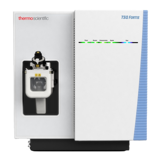
Thermo Scientific TSQ Fortis
Thermo Scientific TSQ 9000
Thermo Scientific TSQ Series
Thermo Scientific TSQ Quantum Access MAX
Thermo Scientific Categories
Laboratory Equipment
Measuring Instruments
Accessories
Freezer
Refrigerator
More Thermo Scientific Manuals
Login
Sign In
OR
Sign in with Facebook
Sign in with Google
Upload manual
Upload from disk
Upload from URL