Sign In
Upload
Manuals
Brands
Thermo Scientific Manuals
Industrial Electrical
Micro-Tech 9101
Thermo Scientific Micro-Tech 9101 Manuals
Manuals and User Guides for Thermo Scientific Micro-Tech 9101. We have
1
Thermo Scientific Micro-Tech 9101 manual available for free PDF download: Reference Manual
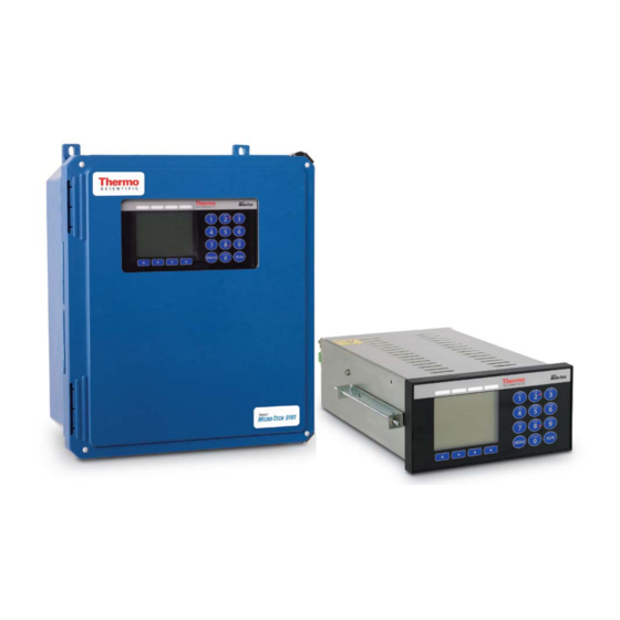
Thermo Scientific Micro-Tech 9101 Reference Manual (329 pages)
Belt Conveyor Scale Integrator
Brand:
Thermo Scientific
| Category:
Industrial Electrical
| Size: 4.01 MB
Table of Contents
Table of Contents
9
Introduction
19
Unpacking the Micro-Tech
19
Overview of the Micro-Tech
19
Figure 1-1. Field-Mounted Version of the Micro-Tech
20
Figure 1-2. Panel-Mounted Version of the Micro-Tech
21
Important Safety Information
22
General Safety Precautions
22
Incoming Power Safety
24
EMC Instructions
25
Hardware Installation
25
Important Wiring and Safety Information
25
Installing the Field Model
26
Figure 1-3. a Typical 9101 Field-Mounted Installation
26
Mounting
27
Connecting the Incoming Power Supply
27
Installing the Panel Model
28
Figure 1-4. Connectors on Underside of Enclosure
28
Mounting
29
Connecting the Incoming Power Supply
29
Configuring Jumpers and Switches
29
Micro-Tech Features
30
Standard Features
30
Inputs and Outputs
30
Micro-Tech Menus and Functions
31
Measuring Functions
31
Monitoring Functions
32
Print Functions
32
Communication Functions
32
Overview of Capabilities
33
Instantaneous Flow-Rate Calculation
33
Flow Totalization
33
Automatic Zero and Span Calibrations
34
Auto Zero Tracking
35
Optional Signal Outputs
35
Symbol Identification
36
Standards Applied
36
Table 1-1. Symbol Identification
36
Specifications
38
Table 1-2. Micro-Tech Technical Specifications
38
Initializing the Micro-Tech
41
Overview
41
Determining the Belt-Scale Code
42
The Quick and Easy Route
42
Acquiring Basic System Data
43
Scale Type Determines Parameters Needed
43
Non-Pivoting Scales
44
Table 2-1. Initialization Data Sheet (Non-Pivoting)
44
The Next Step
45
Pivoting Scales
45
Table 2-2. Initialization Data Sheet (Pivoting)
45
Pivot-To-Load-Cell Distance
46
Number of Weight Idlers
46
Figure 2-1. Pivot-To-Load-Cell Distance
46
Figure 2-2. Number of Weight Idlers
46
Pivot-To-First-Idler Distance
47
Pivot-To-Test-Weight Height
47
Pivot-To-Test-Weight Length
47
Figure 2-3. Pivot-To-First-Idler Distance
47
Figure 2-4. Pivot-To-Test-Weight Height
47
Pivot-To-Carriage Height
48
Roller-To-Stringer Height
48
Number of Load Cells
48
Figure 2-5. Pivot-To-Test-Weight Length
48
Figure 2-6. Pivot-To-Carriage Height
48
Figure 2-7. Roller-To-Stringer Height
48
Idler Spacing
49
Conveyor Angle
49
Figure 2-8. Idler Spacing
49
Figure 2-9. Conveyor Angle
49
Load Cell Capacity, Sensitivity, and Resistance
50
Speed Input
50
Figure 2-10. Location of Load-Cell Data
50
Test Duration
51
Example
51
Manually Determine Test Duration
52
The Next Steps
53
Using the Console
53
Initializing the Software
53
Overview
53
Cold-Starting the Micro-Tech
54
Setting the Date
54
Setting the Time
56
Choosing a Language
58
Entering Scale Data
59
Selecting English/Metric Units
61
Setting the Totalization Units
62
English Totalization Units
62
Metric Totalization Units
63
Setting the Length Units
63
English Length Units
63
Metric Length Units
64
Setting the Rate Units
65
English Rate Units
65
Metric Rate Units
66
Mixed Rate Units
67
Setting the Load-Cell Units
68
Entering the Maximum Scale Capacity
69
Entering the Scale Divisions
70
Entering the Belt-Scale Code
71
Figure 2-11. Belt-Scale-Code Entry Screen
71
Entering the Appropriate Conveyor Data
72
Pivot-To-Load-Cell Distance
73
Number of Weigh Idlers
73
Pivot-To-First-Idler Distance
73
Pivot-To-Test-Weight Height
73
Pivot-To-Test-Weight Length
73
Pivot-To-Carriage Height
73
Roller-To-Stringer Height
73
Number of Load Cells
73
Idler Spacing
74
Conveyor Angle
74
Load Cell Capacity, Sensitivity, and Resistance
74
Setting the Speed Input
74
Establish Test Duration
75
The Next Step
81
Chapter 3 Operation
83
Overview
83
Using the Console
83
Display Screen
83
Keypad
83
Figure 3-1. Main Features of the Micro-Tech Console
83
Soft Key Buttons
84
Status Leds
84
Running the Micro-Tech
85
Run Screen
85
Figure 3-2. Run Screen
85
Viewing the Totals
86
Resetting the Totals
86
Resetting the Reset and Operator Totals
87
Calibrating the Micro-Tech
88
Doing a Zero Calibration
88
Doing an R-Cal Span Calibration
91
Maintenance and Troubleshooting
95
Critical Checkpoints
95
Frequently Asked Questions
96
Load-Cell Problems
97
Overview
97
Four-Wire Load-Cell, No Sense Leads
99
Figure 4-1. Four-Wire Load-Cell, No Sense Leads
99
Four Wire Load-Cell, with Sense Leads
100
Six-Wire Load-Cell with Sense Leads
100
Figure 4-2. Four-Wire Load-Cell, with Sense Leads
100
Analog Input/Output Problems
102
Figure 4-3. Six Wire Load-Cell, with Sense Leads
102
Overview
103
Procedure
104
Figure 4-4. Analog Troubleshooting-Confirm Voltage
104
Figure 4-5. Analog Troubleshooting-Confirm Output
105
Figure 4-6. Analog Troubleshooting-Confirm Loop
105
Figure 4-7. Analog Troubleshooting-Verify Input
106
Figure 4-8. Analog Troubleshooting-Verify Source Output
107
Figure 4-9. Analog Troubleshooting-Verify Ma Loop
107
Opto22 Problems
108
Navigating to the Digital Output Test Screen
108
Test Procedure for the Output Module
109
Figure 4-10. Opto22 Troubleshooting-Output Module
110
Test Procedure for the Input Module
111
Figure 4-11. Opto22 Troubleshooting-Input Module
112
Test Procedure for Eight In/Out Digital Board
113
Figure 4-13. DIO Troubleshooting-Sourcing
114
Figure 4-14. DIO Troubleshooting-Sinking
114
On-Screen Warnings
115
Setting Error
115
Span Out-Of-Range Error
115
Slot #X Change
116
No Speed Pulses
116
Service, Repair, and Replacement Parts
119
Overview
119
Rma
119
Getting Ready to Order
120
Chapter 5 Service, Repair, and Replacement Parts
120
Contacting Thermo Fisher Scientific
121
Parts List
122
Table 5-1. Micro-Tech Parts List
122
Appendix A Additional Installation Information
123
System Data Sheet
123
Door Label
125
Belt-Scale Codes
126
Table A-1. List of Belt-Scale Codes
126
Establishing Belt-Length-Test Duration
130
Acquire Test Duration
130
Partial Belt-Length Method
131
Full Belt-Length Method
134
Material Factoring
137
Reset Weight Factor
137
Static Weight
139
Auto Span
140
Record Results
141
Motherboard Terminal Block Definitions
145
Premium A/D Terminal Block Definitions
147
Motherboard Jumper Locations
148
Premium A/D Jumper Locations
149
Motherboard Jumper Settings
150
Premium A/D Jumper Settings
154
A/D Jumpers-Load-Cell Sense
155
Load-Cell Specifications
155
Table A-2. Motherboard Load-Cell Technical Specifications (Model 9101
155
Table A-3. Premium A/D Board Load-Cell Technical Specifications (Model 9201
156
Programmable Digital Inputs/Outputs
157
Digital Input Expansion Boards
158
DC Input Board
158
Opto22 Input Board
159
Digital Output Expansion Boards
160
Relay Output Board
160
Opto22 Output Board
161
DIO 8In/8Out Board
162
Analog I/O Boards
163
Type A: 4-20Ma Output Board
163
Type B: Analog I/O Board
164
Dual-Plant Load-Cell A/D Board
166
Communication Board
168
Profibus-DP Board
170
Appendix B Micro-Tech Menu Details
173
Overview
173
Main Menu 1
177
Zero Calibration
177
Span Calibration
178
Span Calibration Instructions
182
Span Calibration Menu
185
Material Calibration
187
Main Menu 2
187
Display Menu
193
Scale Data Menu
194
Calibration Data Menu
197
Establish Test Duration
198
Main Menu 3
201
Decreasing the Protection Level
202
On-Line Procedure for Changing Protection Level
203
Protection Menu Table
204
Diagnostics Menu
205
Test Menu
206
USB Menu
208
Formatting a USB Device
208
Printing to a USB Flash Drive
213
Main Menu 4
216
Input/Output Define Menu
216
Alarm Definitions Menu
220
Alarms List
220
Ethernet Settings Menu
225
Main Menu 5
225
Communications Menu
225
Communications Menu Table
225
Profibus Menu
228
Print Menu
228
Main Menu 6
232
Audit Trail Menu
232
Linearization Menu
232
Appendix C Communication Protocols
235
Comm Jumper Configurations
236
Built-In Protocols
237
Protocol Rules
238
Printer
239
Master/Slave Interactions
240
Register Definitions
241
Type, Limits, and Format of Registers
242
Table C-1. Type, Limits, and Format of Registers
242
Description of Registers
243
Bit Definitions
246
Status Bits
246
Alarm Bits
248
I/O Bits
250
Command
255
Siemens 3964R
256
Description
256
Register Mapping
261
Modbus
265
Description
265
Register Mapping
270
Allen-Bradley DF1
272
Description
272
Register Mapping
280
Ethernet Port
284
Ethernet/Ip
284
IP Address
285
Controller Tag Listing Example
286
Ladder Diagram Example
287
Ethernet Module Properties Example
288
General Tab Example
288
Connection Tab
289
Read/Write Registers
290
PLC 5 Data Tables
295
Register Mapping
298
Profibus-DP Protocol
299
Profibus DP
299
Data Transfer
299
Wiring
300
Table C-2. Maximum Cable Length of a Segment
300
Bus Connector
301
Set-Up
301
Table C-3. Bus Connector
301
Slave Address
302
Buffer Dimension
302
Variable Selection
303
Communication
304
Timings
304
Error Management
304
Data Organization
305
Read Operations
305
Table C-5. Read Buffer
305
Table C–4. Data Organization
305
Write Operations
306
Header
306
Data
306
Table C-6. Write Package
306
Diagnostic Data
308
Table C-7. Composition of the Diagnostics Data
308
Register Mapping
310
Block 0
310
Block 1
310
Table C-9. READ BLOCK 1: Batch (Load Out) Function
310
Block 2
311
Block 100
311
Table C-10. READ BLOCK 2: Sets and Thresholds
311
Table C-11. WRITE BLOCK 100: Commands
311
Block 101
312
Block 102
312
Table C-12. WRITE BLOCK 101: Batch (Load out
312
Table C-13. WRITE BLOCK 102: Sets and Thresholds
312
Glossary
313
Attached Drawings
314
Advertisement
Advertisement
Related Products
Thermo Scientific 9101BN
Thermo Scientific 9101SC
Thermo Scientific 9102BNWP
Thermo Scientific 9102SC
Thermo Scientific 9103BNWP
Thermo Scientific 9103SC
Thermo Scientific 9104BNWP
Thermo Scientific 9104SC
Thermo Scientific 9156BNWP
Thermo Scientific 9156SC
Thermo Scientific Categories
Laboratory Equipment
Measuring Instruments
Accessories
Freezer
Refrigerator
More Thermo Scientific Manuals
Login
Sign In
OR
Sign in with Facebook
Sign in with Google
Upload manual
Upload from disk
Upload from URL