Sign In
Upload
Manuals
Brands
Thermo Scientific Manuals
Laboratory Equipment
LTQ XL
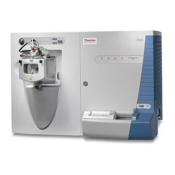
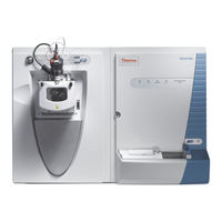
Thermo Scientific LTQ XL Ion Trap Mass Manuals
Manuals and User Guides for Thermo Scientific LTQ XL Ion Trap Mass. We have
3
Thermo Scientific LTQ XL Ion Trap Mass manuals available for free PDF download: Getting Started, Hardware Manual, Getting Started Manual
Thermo Scientific LTQ XL Hardware Manual (174 pages)
Brand:
Thermo Scientific
| Category:
Laboratory Equipment
| Size: 12.42 MB
Table of Contents
Table of Contents
13
Preface
22
Related Documentation
22
Getting a Trap-HCD License
22
Getting a New License Code
23
Installing a New License Code
24
Safety and Special Notices
25
Contacting Us
26
Chapter 1 Introduction
29
LTQ Series Mass Spectrometers
29
Overview of an LC/MS Analysis
32
Chapter 2 Functional Description
35
Overview
35
Figure 1. Functional Block Diagram of an LTQ Series System
36
Syringe Pump
37
Figure 2. Syringe Pump
37
Figure 3. Syringe Pump On/Off Button
37
Divert/Inject Valve
38
Leds and Button
38
Figure 4. Divert/Inject Valve Button and Leds
38
Divert Valve Positions
39
Injection Valve Operation
39
Figure 5. Divert Valve Positions
39
Mass Spectrometer
40
Figure 6. Inject Valve Positions
40
Figure 7. LTQ Series Front Panel Leds
41
Leds
41
Figure 8. Power Panel for the LXQ
42
Figure 9. Power Panel for the LTQ XL and Velos Pro
42
Power Panel
42
API Source
43
Ion Source Interface
43
Figure 10. LXQ Ion Source Interface (Cross Section)
44
Figure 11. LTQ XL Ion Source Interface (Cross Section)
45
Figure 12. Skimmer and Tube Lens (Back View)
46
Figure 13. Velos Pro Ion Source Interface (Cross Section)
46
Figure 14. Velos Pro Exit Lens and S-Lens (Back View)
47
Figure 15. MP00 Rf Lens (LTQ XL on the Left and Velos Pro on the Right)
48
Ion Optics
48
Figure 16. MP0 for the LXQ and LTQ XL
49
Figure 17. MP0 for the LTQ Velos
49
Figure 18. MP0 with a Beam Stop Post for the Velos Pro
49
Figure 19. MP1 Ion Optics
50
Figure 20. LTQ XL Linear Ion Trap Rod Assembly
51
Mass Analyzer
51
Figure 21. Visual Representation of Mass Analyzer Operation
54
Ion Detection Systems
54
Vacuum System
55
Figure 22. Functional Block Diagram of the Vacuum System
56
Figure 23. LXQ Vacuum Manifold with Top Cover Plate and Turbomolecular Pump
57
Figure 24. Turbomolecular Pump
58
Inlet Gases Hardware
59
Cooling Fans
60
Chapter 3 System Shutdown, Startup, and Reset
61
Shutting down the System in an Emergency
61
Opening the Tune Plus Window
62
Figure 25. Tune Plus Window for Velos Pro
62
Placing the Mass Spectrometer in Standby Mode
63
Turning on the Mass Spectrometer
64
Shutting down the Mass Spectrometer Completely
64
Starting the System after a Complete Shutdown
65
Starting the LC System
65
Starting the Data System
66
Starting the Mass Spectrometer
66
Starting the Autosampler
67
Resetting the Mass Spectrometer
67
Resetting Tune and Calibration Parameters
68
Restarting the Data System
69
Turning off Selected Mass Spectrometer Components
69
Chapter 4 Daily Operation
73
Before Operating the LTQ Series System
74
Checking the System Mode
74
Checking the Vacuum Pressure Levels
74
Figure 26. Vacuum Dialog Box
74
Checking the Gas Supplies
76
Checking the ESI Fused-Silica Sample Tube for Elongation
76
After Operating the LTQ Series System
76
Flushing the Sample Transfer Line, Sample Tube, and API Probe
77
Figure 27. APCI Source Dialog Box
77
Figure 28. ESI Source Dialog Box
78
Cleaning the Ion Sweep Cone, Spray Cone, and Ion Transfer Tube
79
Purging the Oil in the Forepump
79
Emptying the Solvent Waste Container
80
Placing the System in Standby Mode
80
Chapter 5 Maintenance
81
Tools and Supplies
83
Ion Source Probe Maintenance
84
ESI Probe Maintenance
85
Figure 29. Two-Piece Fingertight Fitting and Loosened Sample Inlet Adapter Fitting
86
Figure 30. ESI Probe with the Nozzle Removed
88
Figure 31. ESI Nozzle and O-Ring
89
Figure 32. Front End of the ESI Probe (Exploded View)
90
Figure 33. Fused-Silica Sample Tube Inserted through the Front of the ESI Probe
92
Figure 34. Natural PEEK Safety Sleeve Installed in the Sample Inlet (ESI Probe)
93
Figure 35. Natural PEEK Adaptor Fitting Installed to Secure the Safety Sleeve
93
Figure 36. Fingertight Fittings Installed over the Safety Sleeve (ESI Probe)
94
Figure 37. Grounding Union Positioned in the Grounding Bar
94
Figure 38. Safety Sleeve Connection to the Grounding Union (ESI Probe)
95
Figure 39. Sample Tube Securely Tightened to the Grounding Union (ESI Probe)
95
Figure 40. Adjusting the Sample Tube Position (ESI Probe)
96
Figure 41. Sample Tube Position for Flow Rates Greater than 100 Μl/Min (ESI Probe)
96
HESI-II Probe Maintenance
97
Figure 42. Components of the Metal ESI Needle Insert
98
Figure 43. Tip (Enlarged) of the Metal ESI Needle Insert
98
Figure 44. HESI-II Probe Disassembled (Exploded View)
99
Figure 45. HESI-II Probe Nozzle Tip (Enlarged)
99
APCI Probe Maintenance
100
Figure 46. APCI Probe
100
Figure 47. APCI Probe (Cross Section)
101
Figure 48. Sample Inlet End of the APCI Probe Showing Locked and Unlocked
102
Figure 49. APCI Probe Nozzle Assembly
103
Figure 50. 3/8 In. Open-End Wrench on the APCI Flange Fitting
104
Figure 51. APCI Sample Tube Connection
104
Figure 52. Sample Tubing Connection to the APCI Flange Fitting
105
Figure 53. Sample Tube Extending Past the APCI Nozzle Tip
105
Ion Source Interface Maintenance
106
Removing the Ion Source Interface
107
Cleaning the Skimmer and Tube Lens on the LXQ and LTQ XL Mass Spectrometers
108
Figure 54. Ion Source Interface Removed from the Vacuum Manifold
108
Figure 55. Skimmer, Tube Lens, and Ion Source Interface Cage for the LXQ and
109
Cleaning the Exit Lens and S-Lens on the Velos Pro
111
Figure 56. LTQ XL Ion Source Interface Cage
111
Figure 57. Exit Lens, S-Lens, and Ion Source Interface Cage for the Velos Pro
112
Cone
113
Figure 58. Vacuum Dialog Box
114
Figure 59. Inlet Direct Control Dialog Box for an Accela 1250 Pump
114
Figure 60. Ion Sweep Cones
115
Figure 61. Ion Transfer Tube Removal Tool
116
Figure 62. Ion Source Interface Components for the LXQ and LTQ XL
117
Figure 63. Ion Source Interface Components for the Velos Pro
117
Reinstalling the Ion Source Interface
119
MP00 RF Lens Maintenance
119
Removing the MP00 RF Lens Assembly
121
Figure 64. MP00 Rf Lens Assembly Removal
122
Disassembling the MP00 RF Lens Assembly
123
Figure 65. MP00 and Lens L0 Wiring Connections (LTQ XL)
123
Cleaning the MP00 RF Lens Assembly Components
124
Figure 66. MP00 Rf Lens Assembly (LTQ XL)
124
Reassembling the MP00 RF Lens Assembly
125
Reinstalling the MP00 RF Lens Assembly
125
MP0 and MP1 Ion Guides Maintenance
126
Removing the Top Cover of the Mass Spectrometer
127
Figure 67. Front Door Latch
127
Figure 68. Top Cover Screws
128
Figure 69. Top Cover Pushed Back
128
Removing the Vacuum Manifold's Top Cover Plate
129
Figure 70. Electrical Connections to the Top Cover Plate of the Vacuum Manifold
129
Removing the MP0 and MP1 Ion Guides
130
Figure 71. MP0 and MP1 Ion Guides for the LXQ (Exploded View)
132
Figure 72. MP0 and MP1 Ion Guides for the LTQ XL (Exploded View)
133
Figure 73. MP0 and MP1 Ion Guides for the LTQ Velos (Exploded View)
134
Figure 74. MP0 and MP1 Ion Guides for the Velos Pro (Exploded View)
135
Gate Lens
136
Reinstalling the MP0 and MP1 Ion Guides
137
Figure 75. LXQ Wiring Diagram for the MP0 and MP1 Ion Guides
139
Figure 76. LTQ XL Wiring Diagram for the MP0 and MP1 Ion Guides
140
Figure 77. Velos Pro Wiring Diagram for the MP0 and MP1 Ion Guides
141
Reinstalling the Vacuum Manifold's Top Cover
142
Reinstalling the Top Cover of the Mass Spectrometer
143
Electron Multiplier Replacement
143
Figure 78. Electron Multipliers and Dual Anode (LTQ XL)
145
Figure 79. Electron Multipliers and Shield Retainers (Velos Pro)
145
Figure 80. Placement of Screws for the Left and Right Electron Multipliers (Top View)
146
Figure 81. Placement of the Electron Multipliers and Shield Retainers on the Top
146
Figure 82. Diagnostics Dialog Box Showing the Set Device List
147
Figure 83. Diagnostics Dialog Box Showing the Electron Multiplier Voltage Parameters
148
Figure 84. Diagnostics Dialog Box Showing the Mass Calibration Page
149
Figure 85. Calibrate Dialog Box Showing the Automatic Page
150
Figure 86. Semi-Automatic Page in the Calibrate Dialog Box (LXQ and LTQ XL)
151
Figure 87. Semi-Automatic Page in the Calibrate Dialog Box (Velos Pro)
151
Forepump Maintenance
152
Fan Filter Maintenance
152
Chapter 6 Diagnostics
153
Running General Diagnostic Tests
153
Figure 88. Diagnostics Dialog Box Showing the General Test Page
154
Using the Diagnostic Tools
155
Running System Evaluation Tools
155
Figure 89. Diagnostics Dialog Box Showing the System Evaluation Tools Page
155
System Evaluation Tools
156
Chapter 7 Replaceable Parts
159
MS Setup Kit
160
Accessory Kits
160
Chemical Kit
160
Ion Source Probes and Parts
160
Ion Source Interface Parts
161
MP00 Lens Parts
162
MP0 and MP1 Ion Guide Parts
162
Electron Multipliers
163
Miscellaneous Parts
163
Fittings
163
Forepumps
164
Vacuum Manifold Parts
164
Glossary
165
Index
169
Advertisement
Thermo Scientific LTQ XL Getting Started (176 pages)
Brand:
Thermo Scientific
| Category:
Laboratory Equipment
| Size: 11.77 MB
Table of Contents
Table of Contents
7
Preface
11
About this Guide
11
Related Documentation
11
Safety and Special Notices
11
Contacting Us
12
Assistance
12
Changes to the Manual and Online Help
12
Chapter 1 Introduction
13
Introduction
13
Why Use the LTQ XL MS Detector
14
Which MS Detector Technique-ESI or APCI-Is Better for Analyzing My Samples
16
Using ESI/MS
16
Using APCI/MS
17
Should I Use Sheath, Auxiliary, And/Or Sweep Gases
19
How Can I Introduce My Samples into the MS Detector
20
What Types of Buffers Should I Use? What Types Should I Avoid
22
How Should I Set up the MS Detector for Various LC Flow Rates
23
What Is Tuning and Calibration of the MS Detector All about
25
What Is Tuning and Calibration of the MS Detector All about
26
What Is Tuning and Calibration of the MS Detector All about
27
What Types of Experiments Can I Perform with the LTQ XL MS Detector
28
General MS or Msn Experiments
28
Data-Dependent Experiments
29
Ion Mapping Experiments
32
Ion Tree Experiments
35
Chapter 2 Setting up the Ion Source for Tuning and Calibrating the MS
40
Placing the LC/MS System in Standby
40
Removing the APCI Probe
41
Removing the Ion Max Ion Source Housing
45
Installing the Ion Sweep Cone
46
Installing the Ion Max Ion Source Housing
48
Installing the ESI Probe
51
Chapter 3 Tuning and Calibrating Automatically in the ESI/MS Mode
55
Setting up the Syringe Pump for Tuning and Calibration
57
Setting up the MS Detector in the Xcalibur Data System for Tuning and Calibration
59
Tuning the MS Detector Automatically in the ESI/MS Mode
68
Saving Your ESI/MS Tune Method
72
Calibrating the MS Detector Automatically
74
Cleaning the MS Detector after Tuning and Calibrating
77
Tuning with Your Analyte in LC/ESI/MS Mode
81
Chapter 4 Tuning with Your Analyte in LC/ESI/MS Mode
82
Setting up to Introduce Sample by Syringe Pump into Solvent Flow from an LC
83
Setting up to Tune the MS Detector with Your Analyte
86
Optimizing the MS Detector Tune Automatically with Your Analyte
89
Saving the ESI/MS Tune Method
93
Acquiring ESI Sample Data Using the Tune Plus Window
95
Setting up to Acquire MS/MS Data in the Full Scan Type
96
Optimizing the Isolation Width and Setting up to Optimize the Collision Energy
96
Chapter 5 Acquiring ESI Sample Data Using the Tune Plus Window
96
Optimizing the Collision Energy Automatically for an MS/MS Experiment
101
Setting up to Introduce Sample by Loop Injection into Solvent Flow from an LC
104
Acquiring MS Data in the SIM Scan
106
Chapter 6 Setting up the Ion Source for Acquiring Data in APCI/MS/MS
114
Removing the ESI Probe
114
Removing the Ion Max Ion Source Housing
117
Removing the Ion Sweep Cone
118
Installing the Corona Needle
119
Installing the Ion Max Ion Source Housing
120
Installing the APCI Probe
123
Chapter 7 Optimizing the MS Detector with Your Analyte in APCI/MS
127
Mode115
127
Setting up the Inlet for Tuning Using High-Flow Infusion
128
Setting up the MS Detector for APCI/MS Operation
131
Optimizing the Tune of the MS Detector Automatically in APCI/MS Mode
135
Saving the APCI/MS Tune Method
138
Cleaning the MS Detector after Tuning in APCI Mode
140
Acquiring APCI Sample Data Using the Tune Plus Window
143
Setting up to Introduce Sample by Loop Injection into Solvent Flow from an LC
144
Chapter 8 Acquiring APCI Sample Data Using the Tune Plus Window
144
Acquiring APCI Data in the SIM Scan Mode
146
Appendix A Sample Formulations
151
Caffeine, MRFA, and Ultramark 1621 Stock Solutions
152
Stock Solution: Caffeine
153
Stock Solution: MRFA
154
Stock Solution: Ultramark 1621
154
ESI Calibration Solution: Caffeine, MRFA, Ultramark 1621
155
Stock Solution: Reserpine
156
Reserpine Tuning Solution and Reserpine APCI Sample Solution
156
Appendix Bltq XL High Mass Range Calibration
159
High Mass Range Calibration Solution
160
Normal Mass Range Calibration
161
Enter Normal Mass Range Data into Tune Plus
162
Tune on M/Z 524.3
164
High Mass Range Calibration Procedure
166
Notes
171
Index
173
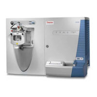
Thermo Scientific LTQ XL Getting Started Manual (74 pages)
LTQ Series
Brand:
Thermo Scientific
| Category:
Laboratory Equipment
| Size: 3.89 MB
Table of Contents
En 61000-3-3: 1995
5
Table of Contents
9
Preface
11
About this Guide
11
Related Documentation
11
Safety and Special Notices
12
Contacting Us
13
Chapter 1 Line Power, Vacuum System, Gases, and Ethernet Communication
15
Connecting the MS Detector to Line Power
15
Connecting the Forepump to the LCQ Fleet or LXQ MS Detector
16
Connecting the Vacuum Hose
16
Connecting the Forepump to the Laboratory Exhaust System
18
Connecting the Forepump to Line Power
19
Connecting the Forepumps to the LTQ XL MS Detector
20
Connecting the Gases to the MS Detector
21
Connecting the Nitrogen Source
21
Connecting the Helium Source
22
Connecting the MS Detector to the Data System Computer
23
Connecting Probes
25
Connecting the ESI Probe to the MS Detector
25
Chapter 2 Connecting Probes
25
Connecting the APCI Probe to the MS Detector
26
Chapter 3 Connecting the MALDI LTQ XL System
27
Connecting the MALDI LTQ XL System Forepumps to Line Power
28
Connecting the MALDI LTQ XL Vacuum System
29
Connecting the MALDI Control Module to the MALDI LTQ XL System
31
Connecting the MALDI CCD Camera to the Data System Computer
34
Chapter 4 Connecting External Devices
37
External Devices Controlled by the Xcalibur Data System
38
Making Contact Closure with Devices Controlled by Xcalibur
38
Selecting the Appropriate Start Instrument
39
External Devices Not Controlled by the Xcalibur Data System
41
Making Contact Closure with Devices Not Controlled by Xcalibur
41
Starting a Sequence Run from Xcalibur
42
Chapter 5 Connecting a Thermo Scientific LC System
47
Contact Closure Cables
48
Making Contact Closure with a Surveyor Plus LC System
49
Making Contact Closure with an Accela LC System
51
Chapter 6 Connecting the Inlet Plumbing
53
Sample Introduction
53
Fittings, Tubing, Unions, and Sample Loops
55
Setting up the Inlet for Direct Infusion
57
Connecting an Infusion Line to the Grounding Union
58
Setting up the Syringe
58
Setting up the Inlet for High-Flow Infusion
59
Connecting the Syringe to the Union Tee
60
Connecting the Union Tee to the Divert/Inject Valve
61
Connecting the Divert/Inject Valve to a Waste Container
62
Connecting the LC Pump to the Divert/Inject Valve
62
Connecting the Union Tee to the Ion Source
63
Setting up the Inlet for Loop Injections (Flow Injection Analyses)
65
Setting up the Inlet for an LC/MS System with an Autosampler
67
Connecting the Grounding Union to the ESI Probe Sample Inlet
69
Chapter 7 Connecting the 4-Port Serial PCB
71
Index
73
Advertisement
Advertisement
Related Products
Thermo Scientific LTQ XL MALDI
Thermo Scientific LTQ Series
Thermo Scientific LTQ ETD
Thermo Scientific LTQ Velos
Thermo Scientific LTQ Velos/ETD
Thermo Scientific LTQ Velos Pro
Thermo Scientific LCQ Fleet
Thermo Scientific Locator
Thermo Scientific Locator Plus
Thermo Scientific Locator Jr. China
Thermo Scientific Categories
Laboratory Equipment
Measuring Instruments
Accessories
Freezer
Refrigerator
More Thermo Scientific Manuals
Login
Sign In
OR
Sign in with Facebook
Sign in with Google
Upload manual
Upload from disk
Upload from URL