Sign In
Upload
Manuals
Brands
Thermo King Manuals
Refrigerator
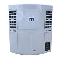
SL-200e
Thermo King SL-200e Manuals
Manuals and User Guides for Thermo King SL-200e. We have
1
Thermo King SL-200e manual available for free PDF download: Maintenance Manual
Thermo King SL-200e Maintenance Manual (342 pages)
Trailer Units
Brand:
Thermo King
| Category:
Refrigerator
| Size: 8.92 MB
Table of Contents
Table of Contents
3
Introduction
11
About this Manual
11
Units Covered
11
Other Reference Manuals
12
Safety Precautions
13
General Practices
13
Auto Start/Stop Controls
13
SL-400E, SLX, Slxe and Slxi with SMART REEFER 2/3 (SR-2/SR-3) CONTROLLER
14
Refrigerant
14
General Information
14
First Aid
14
Refrigerant Oil
14
Electrical
15
Microprocessor Service
15
Welding of Units or Truck Bodies
15
High Voltage
15
Low Voltage
15
Precautions
16
First Aid
16
Unit Decals
16
Specifications
19
Engine
20
Drive System
22
Refrigeration System
23
R-404A/R-452A
23
Heat and Defrost System
24
Controller
25
Electrical Control System
26
Electrical Components
27
Evaporator Fan Motors
27
Electric Standby
29
Electric Drive Motor
29
Standby Power Requirements
29
Remote Evaporator Specifications
29
Maintenance Inspection Schedule
31
All SL and Sle and Spectrum Models Host Unit
32
Remote Evaporators: ECT, ELT, EW, SPECTRUM and TLE
35
All SLX, Slxe Range and Spectrum Models Host Unit
36
SLX, Slxe SPECTRUM
39
All Slxi-100, Slxi-200, Slxi-300, Slxi-400, Slxi SPECTRUM Range
40
Unit Description
45
Single Temperature Systems
46
Multi-Temperature Systems
46
Unit Features
46
Compressors
46
Engines
46
Controllers
46
Service Test Mode (Standard on TG-VI, Μp-IV, Μp-V, Μp-VI, SR-2 and SR-3 Controllers)
47
Electric Standby Motors
47
Refrigeration Modulation Option
47
Discharge Air Modulation Control
47
Electronic Throttling Valve
47
Data Logging Option (Μp-IV, Μp-V, Μp-VI, SR-2 and SR-3 Controllers)
48
Sleep Mode Option (Option on Μp-IV and Μp-V Controllers, Standard on Μp-VI, SR-2 and SR-3 Controllers)
48
Tracking Option (Μp-IV, Μp-V, Μp-V, SR-2 and SR-3 Controllers)
48
CYCLE-SENTRY (Start/Stop) Control Option
48
Economy Mode Control Option
49
Optiset™ Option
50
Data Acquisition System (DAS) Option
50
Remote Control Options (SR-3, SR-2, TG-V, Μp-IV Multi-Temp, Μp-V and Μp-VI Controllers)
50
Sequence of Operation
50
100, SL-100E, SL-200 and SL-200E (TG-VI Controller)
54
Μp-IV or Μp-V Controller)
55
(Μp-IV or Μp-V Controller)
55
400, Sle-400, Slx/Slxe/Slxi and Slx/Slxe/Slxi Spectrum
57
Controller)
57
Thermo King SR Basic Operational Sequence Diesel Mode
60
Operation
60
Thermo King SR Basic Operational Sequence Electric Standby Mode
62
Operation
62
Multi-Temp SR-2/SR-3 Controller)
64
Engine Compartment Components
70
Remote Evaporator Unit Description
71
Unit Operation
72
Defrost
72
Operating Modes
72
Unit Features
72
Protection Devices
73
TG-VI, Μp-IV, Μp-V, Μp-VI and SR-2/SR-3 Control Systems
73
Spectrum Remote Evaporator Unit
73
Serial Number Locations
73
Unit Nameplate
73
TLE and SPECTRUM Remote Evaporator Nameplate
73
Engine Nameplate
73
Compressor Nameplate
73
Electric Motor Nameplate
73
Operating Instructions
75
Unit Controls
76
Unit Control Panel
76
SMART REEFER 2/3 Multi-Temp (SR-2/SR-3 MT) Control System
80
HMI Control Panel
81
Display
82
Control Panel Keys (Single or Multi-Temp SR-2/SR-3)
83
Unit Operation (Single or Multi-Temp SR-2/SR-3)
84
Manual Pretrip Inspection (before Starting Unit)
84
Turning Unit on (Single or Multi-Temp SR-2/SR-3)
85
Turning Unit off (Single or Multi-Temp SR-2/SR-3)
86
Standard Display
87
Operating the Unit in Single Zone Control Mode
88
Standard Display Variations
89
Alarm Display
89
Temperature Watch Display
90
Other Unit Controls
90
Unit Instruments
92
Unit Protection Devices
94
Unit Operation
94
Visual Pre-Trip Inspection
94
Selection of Operating Modes on CYCLE-SENTRY Equipped Units
96
Starting Units on Continuous Run, Diesel Operation
97
Starting Units on CYCLE-SENTRY, Diesel Operation
97
Starting Model 50 Units on Electric Standby Power
98
After Start Inspection
98
Loading Procedure
99
Post Load Procedure
100
Post Trip Inspection
100
Controller Operation
101
Thermoguard Multi-Temp MT Μp-IV and Μp-V Controllers
102
Entering Setpoint Temperature
103
Selecting CYCLE-SENTRY or Continuous Run Mode (Multi-Temp MT Μp-IV and Μp-V ONLY)
103
Initiating Manual Defrost
103
Viewing Information (Display) Screens
104
Checking the Software Version
105
Displaying and Clearing Alarm Codes
105
Unit Pre-Trip Test
106
Thermoguard TG-VI Controller
107
Entering Setpoint Temperature
108
Selecting CYCLE-SENTRY or Continuous Run Mode
108
Initiating Manual Defrost
109
Checking the Software Version
109
Displaying and Clearing Alarm Codes
109
Viewing Information (Display) Screens
109
Unit Self-Check Test
110
Multi-Temp Remote Control Panel
111
Displaying Operating Data
112
Entering Setpoint Temperature
112
Thermoguard Μp-VI Controller
113
Entering Setpoint Temperature
114
Selecting CYCLE-SENTRY or Continuous Run Mode
114
Initiating Manual Defrost
114
Selecting Economy Mode - Revision 4000 and 4010 Software Only
115
Viewing Information (Display) Screens
115
Checking the Software Version
117
Displaying and Clearing Alarm Codes
118
Unit Pre-Trip Test
118
Entering a Start of Trip in the Data Logger
119
SR-2/SR-3 Controller
120
HMI Control Panel
120
Changing the Setpoint
121
Selecting CYCLE-SENTRY or Continuous Mode
121
Initiating a Manual Defrost Cycle
121
Terminating a Defrost Cycle
121
Viewing Gauge Readings
121
Viewing Sensor Readings
122
Navigating the Operator Menu
122
Alarm Codes for Μp-IV, Multi-Temp Μp-IV, Μp-V, Μp-VI, TG-VI , SR-2 and SR-3 Controllers
125
Telematic Status Alerts for TK Bluebox
127
Electrical Maintenance
129
Alternator (Australian Bosch)
130
Charging System Diagnostic Procedures
130
Field Current Test
133
Alternator Removal
134
Alternator Disassembly
134
Inspecting and Diagnosing Components
136
Alternator Assembly
138
Alternator Installation
140
Alternator (Thermo King)
141
Alternator Removal
143
Battery
143
Unit Wiring
144
12 VDC CHARGING SYSTEM
144
Fuse Link
144
Fuses
145
Fuses (Units with TG-VI, MT Μp-IV, Μp-V, Μp-VI, SR-2 or SR-3)
145
Relay Board
146
TG-VI, MT Μp-IV, Μp-V, Μp-VI, SR-2 or SR-3 Controller
147
Air Heater
148
Low Oil Level Switch
149
Switch Test
149
Switch Removal and Installation
149
Bench Test
149
High Water Temperature Switch
150
Switch Test
150
Condenser and Evaporator Fan Rotation (Electric Standby Operation)
150
Evaporator Heaters
151
SL, SLE, SLX, Slxe, Slxi
151
AC Components (Model 50 Units)
151
Electrical Contacts
151
Overload Relay
151
Phase Indicator
151
Phase Correction Option
152
Diagnosing the Phase Correction System
152
Defrost System
154
Defrost Cycle
154
Defrost Cycle Checkout Procedure
154
Defrost Components
155
Engine Maintenance
157
Engine Lubrication System
158
Engine Oil Change
158
Oil Filter Change
158
Crankcase Breather
158
TK 482, TK 486, TK 486V Engines
158
Engine Air Cleaner
159
Dry Type
159
Cyclonic Air Cleaner
161
Engine Cooling System
162
Antifreeze Maintenance Procedure
162
ELC (Extended Life Coolant)
165
Checking the Antifreeze
166
Changing the Antifreeze
166
Bleeding Air from the Cooling System
166
Engine Thermostat
167
Engine Fuel System
168
TK 482, TK 486 and TK 486V
169
Maintenance
170
Bleeding the Fuel System
170
Water in the Fuel System
171
Single Element Fuel Filter/Water Separator Replacement
172
TK 482, TK 486 and TK 486V Engines
173
Integral Fuel Solenoid - TK 482, TK 486 and TK 486V
173
Diagnosing the Integral Fuel Solenoid System
174
Fuel Solenoid Replacement
178
Injection Pump Service and Timing
178
Injection Pump Installation & Timing
178
TK 482, TK 486 and TK 486V Engines
180
TK 482, TK 486 and TK 486V Engines
185
Belt Tension Adjustment and Belt Replacement
187
SL Belt Adjustments
188
Sle, SLX, Slxe, Slxi and Spectrum Belt Adjustments
192
Blower Belts - Upper and Lower Poly-V Groove Belt Replacement on SL Units and Upper Belt Only on SLX, Slxe, Slxi
193
SLX, Slxe, Slxi Belt Replacement
195
SLX, Slxe Upper Belt Replacement
196
Slxe (from October 2016) and Slxi Upper Belt Replacement
198
Compressor Drive Belt Replacement and Adjustment (Model 50)
201
Lower (Engine to Electric Motor or Cross Shaft) Belt (SLX ONLY)
203
SLX Retrofit Clutch Tensioner
204
Clutch Drive Tensioning Schematic Slxe and Slxi
206
Clutch Maintenance
209
SL and Sle Models
211
10 Refrigeration Maintenance
213
Service Tools
214
Leak Detection
214
Compressor Oil
214
Vacuum Pumps
214
Gauge Manifold Sets
214
System Clean-Up
214
Refrigerant Recovery
214
Refrigeration Maintenance Procedures
215
Additional Information Low Side Pump down for TCI and SPECTRUM Models
215
Compressor Oil Acid Test
216
Checking Compressor Oil
216
Refrigerant Charge
217
Checking Refrigerant Charge with an Empty Trailer
217
Checking Refrigerant Charge with a Loaded Trailer
217
Refrigerant Overcharge Check
218
Moisture Indicating Sight Glass (Where Fitted)
219
Moisture Indicating Sight Glass
219
SLX, Slxe, Slxi Spectrum Charging Procedures
220
Micro-Channel Condenser and Auxiliary Receiver Design
220
Charging Procedure for SLX SPECTRUM Categories
220
SLX, Slxe, Slxi SPECTRUM Charging Procedure
221
Refrigerant Leaks
222
Evacuating and Charging Smart Reefer Multi-Temp Systems
222
Set-Up Unit
222
System Evacuation
222
Evacuation Is Important and Critical to System Performance
222
Set-Up and Test Evacuation Equipment
225
Unit Evacuation
227
Unit Charging
228
Remove Evacuation Hoses
230
High Pressure Cutout
230
Head Pressure Control Switch (SL TCI and SL Spectrum)
230
Three-Way Valve Condenser Pressure Bypass Check Valve
230
Modulation Valve
231
Electronic Throttling Valve (ETV)
232
Hot Gas Bypass Valve
232
Spectrum Multi-Temperature Refrigeration Components
233
Host Unit Components
233
Zone Refrigeration Control Components
233
Refrigeration Service Operations
235
Refrigeration System Components
236
Low Side Pump down
236
Compressor
236
High Pressure Cutout Switch or High Pressure Cycle (Control) Switch
237
Condenser Coil
238
Discharge Vibrasorber
238
Suction Vibrasorber
238
Receiver Tank
240
Bypass Check Valve
240
High Pressure Relief Valve
241
Dehydrator (Filter-Drier)
241
Expansion Valve Assembly
241
Evaporator Coil
242
Heat Exchanger
243
Accumulator
243
Pilot Solenoid
244
Modulation Valve (SL and SLE Only)
244
Hot Gas Bypass Solenoid Valve
244
Modulation Valve
244
Throttling Valve (Non-ETV Units)
245
Three-Way Valve Condenser Pressure Bypass Check Valve Repair
248
Three-Way Valve Repair
249
External Compressor Oil Filter - X214, X426 or X430 Compressor
251
Electronic Throttling Valve (ETV)
252
Multi-Temperature System Components
256
Discharge Pressure Sensor
256
Liquid Line Solenoid Valve (LLS, LLS2, LLS3, RLLS or CLLS) or Suction Line Solenoid Valve (SLS, SLS2, SLS3, RSLS or CSLS)
256
Condenser Inlet Solenoid Valve (CIS) or Hot Gas Solenoid Valve (HGS, HGS2, HGS3, RHGS, HGBP or CHGS)
257
Suction Line Check Valve (SLCV, SLCV2, SLCV3, RSLCV or CSLCV), Purge Check Valve (PCV) or Liquid Return Check Valve (LRCV, LRCV2, LRCV3, RLRCV or CLRCV)
257
Condenser Inlet Solenoid Valve (CIS) or Hot Gas Solenoid Valve (HGS, HGS2, HGS3
257
Receiver Tank Pressure Solenoid Valve (RTPS)
258
Purge Valve (PV)
258
12 Structural Maintenance
259
Unit and Engine Mounting Bolts
260
Unit Inspection
261
Defrost Drains
261
Condenser, Evaporator and Radiator Coils
261
Micro-Channel Coil Cleaning Recommendations
261
Unit Installation
263
SL and Sle Top Center Nut
264
Access to Mounting Holes SLX, Slxe, Slxi
265
Access to Mounting Holes Slx/Slxe/Slxi
265
Defrost Damper
266
Damper Door Motor with Current Sensing Blade Position Control
280
And Late Model SL Units)
280
Damper Door Motor with Current Sensing Blade Position Control (Slxi, Slxe, SLX, Sle and Late Model SL Units)
280
Fan Shaft Assembly
285
SL and Sle
285
SL and Sle
294
Slxi, Slxe, SLX Fan Shaft Assembly
299
Lower Blower Assembly Slxi, Slxe, SLX
300
Jackshaft/ Cross Shaft Assembly
301
Sle and SPECTRUM
303
Slxi, Slxe, SLX Cross Shaft Assembly
307
Remote Evaporator Unit
308
Unit Inspection
308
Defrost Drains
308
Evaporator Coil
308
13 Mechanical Diagnosis
309
TK 482, TK 486 and TK 486V Engines
310
Refrigeration System Diagnosis
317
All Models Except TCI and SPECTRUM
318
TCI and SPECTRUM Models
320
Remote Evaporator System Diagnosis
321
Single Temperature Refrigeration System Diagrams
323
Sl/Sle 100, 200 and SLX, Slxe, Slxi 100, 200 WITHOUT MODULATION
324
Cooling Cycle
324
Heat and Defrost Cycles
325
Sle 200 and 300
326
Cooling Cycle with Modulation
326
Heat and Defrost Cycles with Modulation
327
SL-400 and SL-400E
328
Cooling Cycle with Modulation
328
Heat and Defrost Cycles with Modulation
329
SLX 200 PPP, 300, 400, Slxe 300, 400 and SLXI 300, 400
330
Cooling Cycle with Modulation
330
Heat and Defrost Cycles with Modulation
331
Multi-Temperature Refrigeration System Diagrams
333
Sl Tci, or Spectrum
334
Zone 1* on Cool and Zone 2** on Cool
334
Zone 1* on Cool and Zone 2** on Heat
335
Zone 1* on Cool, Zone 2** on Cool and Zone 3*** on Cool
336
Zone 1* on Cool, Zone 2** on Cool and Zone 3*** on Heat
337
SLX, Slxe, SLXI Spectrum
338
Zone 1* on Cool, Zone 2** on Heat
338
Wiring Diagrams and Wiring Schematics
341
Advertisement
Advertisement
Related Products
Thermo King SL-200
Thermo King SL-100
Thermo King SL-400
Thermo King SL-TCI
Thermo King SL-100e
Thermo King SL-400e
Thermo King SLX-300
Thermo King SLX-400
Thermo King SLX SPECTRUM
Thermo King SLX Whisper
Thermo King Categories
Refrigerator
Automobile Accessories
Air Conditioner
Portable Generator
Heat Pump
More Thermo King Manuals
Login
Sign In
OR
Sign in with Facebook
Sign in with Google
Upload manual
Upload from disk
Upload from URL