Sign In
Upload
Manuals
Brands
Textron Manuals
Lawn Mower
JACOBSEN GP400
Textron JACOBSEN GP400 Ride-on Mower Manuals
Manuals and User Guides for Textron JACOBSEN GP400 Ride-on Mower. We have
2
Textron JACOBSEN GP400 Ride-on Mower manuals available for free PDF download: Technical/Repair Manual, Safety, Operation And Maintenance Manual
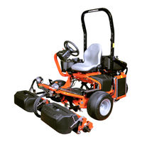
Textron JACOBSEN GP400 Technical/Repair Manual (354 pages)
Riding Greens Mower
Brand:
Textron
| Category:
Lawn Mower
| Size: 38.74 MB
Table of Contents
Chapter 1 Safety 1
9
Table of Contents
9
Introduction
10
Prepare for the Job
10
Safety Label Locations
10
Safety Notices
10
Inspect Safety Labels
14
Keep Work Area Clean
14
Keep Work Area Well Ventilated
14
Park Mower Safely
14
Use Proper Eye and Face Protection
14
Support Machine Securely
15
Use Compressed Air and Air Tools Safely
15
Use Lifting Equipment Safely
15
Handle Fuel Safely
16
Service Tires Safely
16
Store Volatile and Hazardous Materials Safely
16
Handle Chemical Products Safely
17
Service Cooling System Safely
17
Service Hydraulic System Safely
17
Dispose of Waste Materials Safely
18
Service Electrical Components Safely
18
Chapter 2 Specifications and General Information
19
Engine Serial Number
20
Machine Identification
20
Machine Serial Number
20
Optional Machine Accessories
20
Component Location
21
Specifications
22
Quick Reference Specifications
22
Standard Torque Values
29
Inch Fastener Torque Values
29
Metric Fastener Torque Values
29
Hydraulic Hose, Tube, and Fitting General Instructions
30
O-Ring Installation
30
Hose Installation
30
Chapter 3 Engine
31
Fuel System Capacity
32
General Engine Specifications
32
Specifications
32
Component Location
33
Diesel Models
33
Gasoline Models
35
Checks and Adjustments-Diesel Models
36
Purging the Fuel System (Diesel)
36
Repair-Diesel Models
37
Fan Belt (Diesel)
37
Air Filter Assembly (Diesel)
38
Throttle Cable (Diesel)
39
Muffler (Diesel)
40
Coolant Recovery Bottle (Diesel)
40
Thermostat (Diesel)
41
Radiator (Diesel)
42
Fuel Filter (Diesel)
44
Fuel Pump (Diesel)
45
Engine (Diesel)
45
Engine Service (Diesel)
47
Repair-Gasoline Models
48
Air Filter Assembly (Gasoline)
48
Canister (Gasoline)
48
Muffler Assembly (Gasoline)
49
Throttle Cable (Gasoline)
50
Choke Cable (Gasoline)
50
Fuel Filter (Gasoline)
51
Engine (Gasoline)
51
Engine Service (Gasoline)
52
Chapter 4 Electrical
53
Repair Specifications
55
Specifications
55
Test and Adjustment Specifications
55
Theory and Diagnostic Information
56
Electrical Component Symbols
56
Electrical Schematic Component Identification
59
Electrical Schematic
60
Power Circuit-Theory of Operation
66
Diesel Engine Circuit-Theory of Operation
67
Diesel Engine Circuit Schematic
68
Gasoline Engine Circuit-Theory of Operation
71
Gasoline Engine Circuit Schematic
72
Raise/Lower Circuit-Theory of Operation
75
Raise Circuit Schematic
75
Lower Circuit Schematic
75
Mow Circuit-Theory of Operation
78
Mow Circuit Schematic
79
Backlap Circuit-Theory of Operation
80
Backlap Circuit Schematic
81
Work Light Circuit-Theory of Operation
82
Work Light Circuit Schematic
83
Instrumentation Circuit-Theory of Operation
85
Instrumentation Circuit Schematic
86
Troubleshooting
88
Power Circuit
88
Glow Plug Circuit
88
Start Circuit
88
Charging Circuit
89
Raise/Lower Circuit
89
Mow Circuit
89
Backlap Circuit
89
Work Light Circuit
90
Instrumentation Circuit
90
Horn and Audible Alert Circuit
91
Component Tests and Adjustments
92
Electrical System and Component Testing
92
Fuses Test
93
Relays Test
93
Engine Stop Relay (Gasoline)
94
Key Switch Test
94
Rocker Switches Test
95
Backlap Switch Test
96
Horn Switch Test
96
Raise/Lower Switch Assembly Test
97
Seat Switch Test
98
Raise/Lower Solenoid Test
98
Mow Solenoid Test
99
Fuel Shutoff Solenoid Test
99
Fuel Shutoff Timer Test
100
Carb Solenoid Test (Gasoline)
100
Mow/Transport Switch Adjustment
101
Repair
102
Control Module
102
Battery Cover
102
Battery
103
Alternator
103
Starter Motor
104
Instrument Panel
104
Rocker Switches
105
Horn Switch
106
Key Switch
106
Raise/Lower Switch Assembly
107
Mow/Transport Switch
108
Backlap Switch
108
Engine Oil Pressure Switch (Diesel)
109
Engine Oil Pressure Switch (Gasoline)
109
Hydraulic Oil Charge Filter Pressure Switch
110
12V Accessory Socket
111
Fuses
112
Relays
112
Engine Temperature Sensor
113
Lower Solenoid
113
Raise Solenoid
114
Mow Solenoid
114
Fuel Shutoff Solenoid
115
Warning Lights
115
Fuel Shutoff Timer
116
Hour Meter
117
Horn
117
Chapter 5 Hydrostatic Power Train
119
Repair Specifications
121
Specifications
121
Test Specifications
121
Hydraulic Hose, Tube, and Fitting General Instructions
122
O-Ring Installation
122
Hose Installation
122
Portable In-Line Filter
123
Component Location
124
Theory of Operation and Sub-Circuit Schematics
125
Traction Circuit-Neutral Schematic and Theory of Operation
125
(2WD Models)
125
Traction Circuit-Neutral Schematic (2WD Models)
126
Traction Circuit-Forward Schematic and Theory of Operation (2WD Models)
129
Traction Circuit-Forward Schematic (2WD Models)
130
Traction Circuit-Reverse Schematic and Theory of Operation (2WD Models)
133
Traction Circuit-Reverse Schematic (2WD Models)
134
Traction Circuit-Neutral Schematic and Theory of Operation (3WD Models)
137
Traction Circuit-Neutral Schematic (3WD Models)
138
Traction Circuit-Forward Schematic and Theory of Operation (3WD Models)
141
Traction Circuit-Forward Schematic (3WD Models)
142
Traction Circuit-Reverse Schematic and Theory of Operation (3WD Models)
145
Traction Circuit-Reverse Schematic (3WD Models)
146
Troubleshooting
148
Tests and Adjustments
150
Neutral Adjustment
150
Field Test Procedures
152
Preliminary Checks
152
Charge Pump Test
152
Traction System Test
152
Instrument Test Procedures
153
Instrument Test Overview
153
Charge Pressure Test
154
Traction System Test
155
Traction Pump Tests
159
Wheel Motors Tests
161
Flushing Valve Check Valve Test
166
Repair
168
Traction Pump and Control
168
Flushing Valve
173
Wheel Motors
175
Chapter 6 Hydraulics
193
Hydraulic Hose Installation
196
Hydraulic Hose, Tube, and Fitting General Instructions
196
O-Ring Installation
196
Component Location
197
Hydraulic Schematic (3WD)
199
Hydraulic Schematic (2WD)
204
Theory of Operation and Sub-Circuit Schematics
210
Steering Circuit Schematic and Theory of Operation
210
Steering Circuit Schematic
211
Raise Circuit Schematic and Theory of Operation
212
Raise Circuit Schematic
213
Lower Circuit Schematic and Theory of Operation
214
Lower Circuit Schematic
215
Mow Circuit Schematic and Theory of Operation
216
Mow Circuit Schematic
217
Backlap Circuit Schematic and Theory of Operation
218
Backlap Circuit Schematic
219
Field Test Procedures
220
Preliminary Checks
220
Lift Cylinder Leakage Test
220
Steering Leakage Test
221
Reel Motor Case Drain Test
222
Instrument Test Procedures
223
Instrument Test Overview
223
Cutting Units Circuit Test
224
Gear Pump Test
225
Reel Valve Unit Test
227
Reel Motors Test
228
Implement Relief Valve Pressure Test
231
Lift Relief Valve Pressure Test
233
Hydraulic Oil Tank-Drain Procedure
234
Repair
234
Gear Pump
235
Lift Valve
238
Reel Valve Unit
240
Soft Drop Valve
242
Top and Bottom Sequence Valves
243
Center Lift Cylinder
244
Left and Right Front Lift Cylinders
246
Hydraulic Oil Tank (Diesel)
249
Hydraulic Oil Tank (Gasoline)
250
Hydraulic Oil Charge Filter Assembly
251
Hydraulic Oil Cooler (Diesel)
252
Hydraulic Oil Cooler Assembly (Gasoline)
253
Chapter 7 Steering
255
Specifications
256
Component Location
257
Repair
258
Steering Column Covers
258
Steering Wheel
258
Control Arm
259
Steering Unit
260
Steering Cylinder
268
Steering Yoke Assembly
271
Chapter 8 Cutting Units
273
Component Location
275
Quality-Of-Cut Troubleshooting
276
Troubleshooting
276
Mechanical Troubleshooting
288
Checks and Adjustments
289
Bedknife-To-Reel Clearance Adjustment
289
Height-Of-Cut (HOC) Adjustment
290
Grass Shield Adjustment
290
Reel Bearing Pre-Load Adjustment
291
Reel Leveling Rod Pre-Adjustment
292
Cutting Unit Leveling Adjustment
293
Repair
294
Cutting Unit
294
Lift Yoke
295
Reel Leveling Rod
295
Swing Arm
299
Reel Motor
300
Grass Shield
304
Bedknife Backing Assembly
304
Bedknife
305
Reel Bearing Housing Assembly
306
Reel Assembly
309
Front Roller
310
Rear Roller
310
Roller Bearings
311
Chapter 9 Accessories and Miscellaneous Repair
313
Specifications
314
Component Location
315
Checks and Adjustments
316
Raise Hydraulic Oil/Fuel Tank
316
Rotate Seat Forward
316
Transport Speed Stop Adjustment
317
Mow Speed Stop Adjustment
318
Park Brake Adjustment
318
Repair
319
Ops
319
Fuel Tank (Diesel)
319
Fuel Tank (Gasoline)
321
Fuel Tank Support Pan
322
Traction Pedal Assembly
323
Instrument Panel Cover
325
Traction Lever Assembly
325
Throttle Lever
326
Park Brake Lever
326
Seat and Seat Plate
327
Seat Switch
328
Tool Box
329
Floorboard Assembly
329
Splash Shield
330
Work Light
331
Front Wheel
331
Park Brake Caliper Assembly
332
Park Brake Cables
332
Front Wheel Hub
334
Rear Wheel and Steering Axle-2WD Units (Diesel)
334
Steering Axle-2WD Units (Diesel)
335
Rear Wheel and Steering Axle-2WD Units (Gasoline)
336
Steering Axle-2WD Units (Gasoline)
337
Rear Wheel-3WD Units
337
Rear Wheel Hub-3WD Units
338
Advertisement
Textron JACOBSEN GP400 Safety, Operation And Maintenance Manual (108 pages)
Greens Mower
Brand:
Textron
| Category:
Lawn Mower
| Size: 10.52 MB
Table of Contents
Table of Contents
2
Important
3
Product Identification
4
Guidelines for the Disposal of Scrap Products
6
During Service Life
6
End of Service Life
6
Parts Manual
7
Key Numbers
8
Safety
8
How to Operate Safely
9
Safe Operation
9
Preparation
9
Operation
10
Rops
11
Safe Handling of Fuels
11
Maintenance and Storage
11
When You Put the Mower on a Trailer
12
Important Safety Notes
13
Specification
16
Engine Specification
16
Dimensions & Weights
17
Machine Specification
18
Vibration Level
19
Noise Level
20
Slopes
20
Cutting Unit Specification
21
Cutting Performance
21
Recommended Lubricants
22
Accessories
22
Certificates of Conformity
23
Notes
27
Decals
28
Safety Decals
28
Instruction Decals
30
Notes
31
Controls
32
Operator Workstation
32
Instrument Panel
33
Starter Key Switch
34
Throttle Control Lever
34
Cutting Unit Switch (PTO)
34
Engine Coolant Temperature (Diesel Only)
35
Working Lights
35
Hour Meter
35
Blocked Hydraulic Filter Warning Light
36
Multifunction Warning Light
36
Oil Pressure Warning Light
36
Choke Control (Gasoline Only)
36
Mow / Transport Lever
37
Power Outlet
37
Horn Button
37
Parking Brake
37
Traction Pedal
38
Steering Wheel
38
Lift & Lower Rate & Synchronisation Control
38
Free Wheel
39
Operation
40
Daily Inspection
40
Operator Presence and Safety Interlock System
40
Operating Procedure
41
Setting up the Machine
43
Mounting the Cutting Heads
44
Reel Motor Mounting
45
Cutting Cylinder Lift & Lower Synchronisation
46
Operation of the Machine
46
Starting the Engine
47
Driving
47
Mowing Procedure
47
To Stop the Engine
48
How to Remove a Blockage from Cutting Units
48
Backlapping
49
Backlapping Procedure
50
Transporting on a Trailer or Flatbed
50
Slinging and Jacking the Machine
50
Mowing on Slopes
51
Slope Calculation Chart
53
Maintenance and Lubrication
54
Maintenance and Lubrication Chart
54
Engine Lubrication - Gasoline
54
Engine Lubrication - Diesel
56
Engine Access
58
Engine Oil Level - Gasoline
58
Engine Oil Change- Gasoline
59
Engine Oil Filter- Gasoline
59
Air Filter - Gasoline
60
Engine Fuel Filter - Gasoline
61
Oil Cooler Gasoline Machine
61
Air Filter - Diesel
63
Engine: Fan Belt - Diesel
63
Engine Coolant - Diesel
64
Oil Cooler and Radiator - Diesel
65
Bleeding the Fuel System - Diesel
66
Air Cleaner - Diesel
67
Battery - Gas & Diesel
67
Hydraulic System - Gas & Diesel
68
Handbrake - Gas & Diesel
69
Tyres - Gas & Diesel
69
Machine Maintenance General - Gas & Diesel
70
Lubrication of Cutting Unit
70
Notes
71
Adjustments
72
Traction Control Pedal
72
Adjusting Speed Control Switch
73
Steering Arm Adjustment
73
Rear Swing out Arm
74
Levelling Linkage for the Front Cutting Heads
75
Seat Adjustment
76
Bedknife-To-Reel Trueset™ Reel
81
Bedknife Adjustment Trueset™ Reel
82
Cutting Height Trueset™ Reel
83
Reel Beartrueset™ Reel
84
Bedknife Adjuster Spring Trueset™ Reel
84
Bedknife Adjuster Tension Trueset™ Reel
85
Grinding Bedknife Trueset™ Reel
85
Bedknife Adjustment Classic Xp™ Reels
86
Height of Cut Classic Xp™ Reels
87
Accessories
88
Three Wheel Drive Kit
88
Paddle Kit
88
Dew Whip Kit
89
Groomer Kit
89
Notes
90
Problem Solving
91
Problem Solving General
91
Quality of Cut
92
Quality of Cut Troubleshooting
92
Washboarding
92
Marcelling
93
Step Cutting
94
Scalping
95
Stragglers
96
Streaks
97
Windrowing
98
Rifling or Tramlining
99
Matched Cutting Units
99
FUSES and RELAYS Fuse and Relay Identification
101
Notes
102
Guarantee
103
Warranty
103
Service
103
Evaporative Emission Control Warranty Statement
104
Advertisement
Related Products
Textron Jacobsen Greens King VI 62376
Textron Jacobsen Greens King VI 62375
Textron Jacobsen Greens King VI 62377
Textron Jacobsen Greens King VI 62378
Textron JACOBSEN G-PLEX III DN
Textron JACOBSEN G-PLEX III DP
Textron JACOBSEN G-PLEX III Series
Textron Jacobsen Tri-King 67139
Textron Jacobsen Tri-King 67141
Textron Jacobsen Tri-King 67140
Textron Categories
Lawn Mower
Crimp tool
Power Tool
Cutter
Measuring Instruments
More Textron Manuals
Login
Sign In
OR
Sign in with Facebook
Sign in with Google
Upload manual
Upload from disk
Upload from URL