Sign In
Upload
Manuals
Brands
Texas Instruments Manuals
Motherboard
ADS1299
Texas Instruments ADS1299 Manuals
Manuals and User Guides for Texas Instruments ADS1299. We have
1
Texas Instruments ADS1299 manual available for free PDF download: User Manual
Texas Instruments ADS1299 User Manual (68 pages)
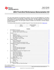
EEG Front-End Performance Demonstration Kit
Brand:
Texas Instruments
| Category:
Motherboard
| Size: 3.46 MB
Table of Contents
Table of Contents
1
ADS1299EEG-FE Overview
4
Important Disclaimer Information
4
Information about Cautions and Warnings
4
Overview
5
Introduction
5
Supported Features
5
Features Not Supported in Current Version
5
ADS1299EEG-FE Hardware
5
Factory Default Jumper Settings
6
ADS1299EEG-FE Kit
6
Software Installation
7
Minimum Requirements
7
Installing the Software
7
Executable to Run ADS1299 Software Installation
7
Initialization of ADS1299EEG-FE
8
License Agreement
8
Installation Process
9
Usbstyx Driver Preinstallation
9
Install the ADS1299 EVM Hardware Drivers
10
Completion of ADS1299 Software Installation
10
New Hardware Wizard
10
New Hardware Wizard Screen 3
11
Completion of the Initial USB Drive
11
Second 'New Hardware" Wizard
12
Install the Usbstyx Driver
12
ADS1299EEG-FE Daughter Card Hardware Introduction
13
Power Supply
14
ADS1299 EEG-FE Front End Block Diagram
14
Clock
15
Power Supply Test Points
15
Analog Supply Configurations
15
Digital Supply Configurations
15
Clock Jumper Options
15
Reference
16
Accessing ADS1299 Analog Signals
16
Accessing ADS1299 Digital Signals
16
External Reference Jumper Options
16
Test Signals
16
Serial Interface Pin out
16
Analog Inputs
17
Input Configurations Supported by the EEG-FE A) Differential Inputs B) Single Ended Inputs
17
Using the Software: ADS1299 Control Registers and GUI
18
Overview and Features
18
File Save Option under 'Save' Tab
18
Global Channel Registers
19
Channel Control Registers
19
Channel Registers GUI for Global Registers
19
Input Multiplexer for a Single Channel (MAIN = [000 or 110 or 111])
20
Channel Control Registers GUI Panel
20
Register Bit for SRB1 Routing
21
Internal Test Signals
21
Simplified Diode Arrangement
22
Eight Channel Read of Internal Temperature Data
22
GPIO and Other Registers
23
Lead-Off and BIAS Registers
23
GPIO Control Register GUI Panel
23
LOFF_STATP and LOFF_STATN Comparators
24
LOFF_SENSP and LOFF_SENSN Registers GUI Panel
24
Lead-Off Status Indicator
25
Register Map
26
BIAS_SENSP and BIAS_SENSN GUI Panel
26
Device Register Settings
26
ADS1299EEG-FE Analysis Tools
27
Scope Tab
27
Scope Tool Features
27
Histogram Tool
28
Zoom Option on the Waveform Examination Tool
28
FFT Tool
29
Histogram Bins for Input Short Noise
29
Analysis : FFT Graph of Input Short Test
30
Analysis : FFT : AC Analysis Parameters : Windowing Options
31
Analysis : FFT : FFT Analysis : Input Short Condition
31
EEG Specific Features
32
Reference Signal and Patient Bias Signal
32
Changing the User-Defined Dynamic Range for Channel 1
32
Dedicated Reference and Bias Electrode
33
Dedicated Reference Drive Options through REF_ELEC
33
Programmable Reference and Bias Electrode
34
Settings for Normal Electrode
35
Configuring BIASREF and Bias Drive Buffer
35
Lead-Off Detection
36
Setting up the Bias Drive Loop
36
Setting the LOFF Register Bits
37
Configuring the Lead off Comparator
37
Lead off Status Registers
37
Scope Tab for Impedance Measurement at 31.25Hz
38
FFT Analysis for Impedance Measurement at 31.25Hz
39
External Calibration/Test Signals
40
Scope Tab for Impedance Measurement at Fdr/4 (DR = 4Ksps)
40
Multiplexer Setting for Calibration with Electrode Disconnected
41
Multiplexer Setting with Positive Electrode Connected to Test Signal
42
Multiplexer Setting with both Electrodes Connected to Test Signal
42
Test Options on the EVM
43
On Chip (ADS1299) Input Short
43
Channel Setting for Input Short Test
43
Global Register Settings for Input Short Test
43
External Input Short with 5K Resistor
44
Scope Tab for Input Short Test
44
Global Register Settings for External Input Short Test
45
Scope Showing Noise for Input Short with 5K Resistors
45
Noise with Common Reference on Negative Inputs
46
MISC1 Register Setting for SRB1
46
Noise with Negative Input Connected to SRB1 Pin
47
Noise with Buffered Common Reference Input
48
Noise with OPA376 in SRB1 Path
48
Internally Generated Test Signal and Other Multiplexer Inputs
49
Arbitrary Input Signal
49
Scope Tab with Sinusoidal Inputs on AIN1
49
Bill of Materials, Layouts and Schematics
50
ADS1299EEG-FE Front-End Board Schematics
50
ADS1299EEG-FC Schematic
50
ADS1299EEG-FC Jumper Schematic
51
ECG Power Supplies
52
Printed Circuit Board Layout
53
External Reference Drivers (Not Installed)
53
ECG MDK Board Interface Adapter
53
ADS1299EEG-FE Top Assembly
54
ADS1299EEG-FE Top Layer
54
ADS1299EEG-FE Internal Layer (1)
55
ADS1299EEG-FE Internal Layer (2)
55
ADS1299EEG-FE Bottom Layer
56
ADS1299EEG-FE Bottom Assembly
56
Bill of Materials
57
ADS1299EEG-FE Power-Supply Recommendations
59
Recommended Power Supply for ADS1299EEG-FE
59
Advertisement
Advertisement
Related Products
Texas Instruments ADS1298ECG-FE
Texas Instruments ADS1298
Texas Instruments ADS1298ECGFE-PDK
Texas Instruments ADS1299EEG-FE
Texas Instruments ADS1261EVM
Texas Instruments ADS125H02
Texas Instruments ADS1282EVM-PDK
Texas Instruments ADS1246EVM
Texas Instruments ADS1282-SP
Texas Instruments ADS1282EVM-CVAL
Texas Instruments Categories
Motherboard
Control Unit
Microcontrollers
Computer Hardware
Calculator
More Texas Instruments Manuals
Login
Sign In
OR
Sign in with Facebook
Sign in with Google
Upload manual
Upload from disk
Upload from URL