Sign In
Upload
Manuals
Brands
Teledyne Manuals
Digital Camera
Linea GigE LA-GM-02K08A
Teledyne Linea GigE LA-GM-02K08A Camera Manuals
Manuals and User Guides for Teledyne Linea GigE LA-GM-02K08A Camera. We have
1
Teledyne Linea GigE LA-GM-02K08A Camera manual available for free PDF download: User Manual
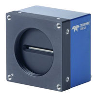
Teledyne Linea GigE LA-GM-02K08A User Manual (139 pages)
Monochrome CMOS Line Scan
Brand:
Teledyne
| Category:
Digital Camera
| Size: 4.15 MB
Table of Contents
Table of Contents
3
Linea Gige Series Overview
7
Description
7
Linea Gige Application Advantages
8
Linea Gige with Turbodrive
8
Linea Gige Firmware
9
Part Numbers and Software Requirements
10
Gige Vision Sapera Application Description
11
Camera Specifications Overview
12
Environmental Specifications
13
Compliance, EMI Certifications
13
Flash Memory Size
13
Sensor Performance
14
Sensor Specifications
14
Spectral Responsivity
15
Effective Quantum Efficiency
15
Connecting the Linea Gige Camera
16
Gige Network Adapter Overview
16
PAUSE Frame Support
16
Connect the Linea Gige Camera
17
Connectors
17
LED Indicators
18
Network Status Indicators
18
Camera Status LED Indicator
18
LED States on Power up
19
Linea Gige IP Configuration Sequence
19
Supported Network Configurations
19
Preventing Operational Faults Due to Esd
20
Using Linea Gige with the Sapera Api
21
Network and Computer Overview
21
Installation
22
Procedure
22
Camera Firmware Updates
22
Gige Server Verification
23
Gige Server Status
23
Optimizing the Network Adapter Used with Linea Gige
24
Running the Network Configuration Tool
24
Quick Startup with Camexpert
25
About the User Defined Camera Name
26
Operational Reference
27
Using Camexpert with Linea Gige Cameras
27
Camexpert Panes
28
Camexpert View Parameters Option
29
Creating a Camera Configuration File in the Host
29
Camera Feature Categories
30
Camera Information Category
31
Camera Information Feature Descriptions
31
Camera Configuration Selection Dialog
34
Camera Power-Up Configuration
34
User Set Configuration Management
34
Sensor Control Category
35
Sensor Control Feature Descriptions
35
Gain and Black Level Control Details
36
Exposure Controls Details
37
Internal Programmable Exposure
37
External Programmable Exposure
37
External Trigger Width Exposure
38
Exposure and Readout Overlap
38
I/O Control Category
39
I/O Control Feature Descriptions
40
I/O Module Block Diagram
45
Trigger Overview
46
Trigger Selector Details
46
Trigger Source Types
47
Input Line Details
47
Output Line Details
48
Example of Free Run Line Mode with Frame Trigger
48
Example of Line Trigger Mode
48
Example of Line Trigger Plus Frame Trigger Combined
49
Counter and Timer Control Category
50
Counter and Timer Control Feature Description
50
Counter and Timer Group Block Diagram
54
Example: Counter Start Source = off
54
Example: Counter Start Source = Counterend (Itself)
55
Example: Counterstartsource = EVENT and Signal (Edge Base)
55
Example: Counterstartsource = Signal (Level Base) Example 1
56
Example: Counterstartsource = Line (Edge Base) Example 2
56
Advanced Processing Control Category
57
Advanced Processing Control Feature Descriptions
57
Flat Field Correction Overview
60
Flat Field Correction Algorithm Description
60
Information on the Sapera Flat Field Coefficients File
61
Important Factors about Flat Field Processing
61
How to Do a FFC Setup Via Sapera Camexpert
62
Set up Dark and Bright Acquisitions with the Histogram Tool
62
Flat Field Correction Calibration Procedure
63
FPN Correction
67
PRNU Correction
68
Cycling Preset Mode Control Category
71
Cycling Preset Mode Control Feature Description
72
Using Cycling Presets-An Example
75
Initial Example Setup
75
Cycling Example: Changing Gain
75
Image Format Control Category
76
Image Format Control Feature Description
76
Pixel Size: Monochrome 12-Bit Packed
80
Binning
80
Internal Test Image Generator
82
Acquisition and Transfer Control Category
82
Acquisition and Transfer Control Feature Descriptions
82
Acquisition Buffering
84
Using Transfer Queue Current Block Count with Camexpert
84
Overview of Transfer Control (Transfercontrolmode)
84
Features that Cannot be Changed During a Sapera Transfer
86
Event Control Category
87
Event Control Feature Descriptions
87
Gige Vision Transport Layer Control Category
92
Gige Vision Transport Layer Feature Descriptions
92
Defaults for Devicepacketresendbuffersize
96
Device Upnp Auto-Discovery Mode Details
96
Enable Windows Network Discovery
96
Accessing the Linea Gige File Memory
98
Using the Linea Gige File Memory
98
Gige Vision Host Control Category
99
File Access Control Category
100
File Access Control Feature Descriptions
100
File Access Via the Camexpert Tool
102
Device Streaming Registers
103
Start - End Command Requirements
103
Network Overview & Tools
104
Ip Configuration Mode Details
104
Link-Local Address (LLA)
104
DHCP (Dynamic Host Configuration Protocol)
105
Persistent IP
106
Technical Specifications
108
Mechanical Specifications
108
Linea Gige 8K
108
Linea Gige 2K and 4K
109
Additional Notes on Linea Gige Identification and Mechanical
110
Sensor Alignment Specification
111
Connectors
112
HD15 Type Connector Details
112
Mating GPIO Cable Assembly
112
Input Signals Electrical Specifications
114
Output Signals Electrical Specifications
116
Computer Requirements for Linea Gige Cameras
117
Host PC System
117
Ethernet Switch Requirements
117
IEEE 802.3X Pause Frame Flow Control
118
Ethernet to Fiber-Optic Interface Requirements
118
Declarations of Conformity
119
FCC Statement of Conformance
119
FCC Class a Product
119
EU and UKCA Declaration of Conformity
119
Additional Reference Information
120
Lens Selection Overview
120
Lens Mount Types
120
Linea Gige 2K and 4K
120
M42X1 to Nikon F Bayonet Adapter (AC la 00115 A1-R )
121
M42X1 to C-Mount Adapter (AC-LC-00001-00-R)
122
Linea Gige 8K
123
M72X0.75 to F-Mount Adapter (AC-LN-00001-A0-R)
123
Lens Image Circle Illustration
124
Additional Lens Parameters (Application Specific)
126
Optical Considerations
127
Illumination
127
Light Sources
127
Lens Modeling
128
Magnification and Resolution
128
Sensor Handling Instructions
129
Electrostatic Discharge and the Sensor
129
Protecting against Dust, Oil and Scratches
129
Cleaning the Sensor Window
130
Ruggedized Rj45 Ethernet Cables
131
Troubleshooting
132
Overview
132
Problem Type Summary
132
Verifying Network Parameters
134
Before Contacting Technical Support
134
Installation Issues and Functional Problems
135
Device Available with Operational Issues
135
Firmware Updates
135
Power Failure During a Firmware Update-Now What
135
Cabling and Communication Issues
136
Acquisition Error Without Timeout Messages
137
No Camera Exposure When Expected
137
Camera Is Functional but Frame Rate Is Lower than Expected
137
Camera Acquisition Is Good but Frame Rate Is Lower than Expected
137
Camera Is Functional, Line Rate Is as Expected, but Image Is Black
137
Other Problems or Issues
138
Buffer Incomplete Error Message
138
Issues with Cognex Visionpro
138
Contact Information
139
Sales Information
139
Technical Support
139
Advertisement
Advertisement
Related Products
Teledyne Linea GigE LA-GM-04K08A
Teledyne Linea GigE LA-GM-08K08A
Teledyne Linea Color GigE LA-GC-02k05B
Teledyne Linea Color GigE LA-GC-04k05B
Teledyne Linea CL LA-CM-08K08A
Teledyne Linea CL LA-CM-16K05A
Teledyne Linea CL LA-CM-04K08A
Teledyne Linea CL LA-CM-02K08A
Teledyne Lt-C5500B
Teledyne Lt-C1980B
Teledyne Categories
Measuring Instruments
Analytical Instruments
Digital Camera
Test Equipment
Laboratory Equipment
More Teledyne Manuals
Login
Sign In
OR
Sign in with Facebook
Sign in with Google
Upload manual
Upload from disk
Upload from URL