Sign In
Upload
Manuals
Brands
Tektronix Manuals
Test Equipment
TDS2024C
Tektronix TDS2024C Manuals
Manuals and User Guides for Tektronix TDS2024C. We have
6
Tektronix TDS2024C manuals available for free PDF download: User Manual, Technical Reference, Service Manual, Security Instructions
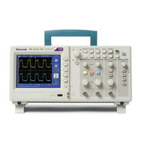
Tektronix TDS2024C Technical Reference (130 pages)
TDS2000C Series Digital Storage Oscilloscopes
Brand:
Tektronix
| Category:
Oscilloscope
| Size: 10.53 MB
Table of Contents
Table of Contents
5
General Safety Summary
10
Service Safety Summary
12
Preface
13
Manual Conventions
13
Related Documentation
13
Specifications
15
Signal Acquisition System Characteristics
17
Table 1-1: Signal Acquisition System Characteristics
17
Time Base System
21
Table 1-2: Time Base System
21
Triggering System
23
Table 1-3: Triggering System
23
Display Specifications
27
Table 1-4: Display Specifications
27
Interfaces and Output Ports Specifications
28
Data Handling Characteristics
28
Power Distribution System
28
Table 1-5: Interfaces and Output Ports Specifications
28
Table 1-6: Data Handling Characteristics
28
Table 1-7: Power Distribution System
28
Mechanical Characteristics
29
Environmental Performance
29
Table 1-8: Mechanical Characteristics
29
Table 1-9: Environmental Performance
29
Data Logging System Characteristics
30
Limit Testing System Characteristics
30
Table 1-10: Data Logging System Characteristics
30
Table 1-11: Limit Testing System Characteristics
30
Where to Find Operating Information
33
Theory of Operation
37
System Level Block Diagrams
40
Figure 3-1: Module-Level Block Diagram (2-Channel)
40
Figure 3-2: Module-Level Block Diagram (4-Channel)
41
Main Board
42
Acquisition System
42
Input Signal Interface
43
Probe Compensation
43
External Trigger
43
Main Board Power
43
Power Supply
44
Display Module
44
Front Panel
44
Table 4-1: Performance Verification
47
Four-Channel Oscilloscopes
48
Performance Verification
48
Test Record
48
Table 4-2: Test Record
48
Performance Verification Procedures
49
Self Test
49
Self Calibration
49
Check DC Gain Accuracy
49
Check Bandwidth
51
Check Edge Trigger Sensitivity
53
Check Vertical Position Accuracy
56
Figure 4-1: Example of a Line Graph for the Vertical Position Accuracy Test
59
Adjustment Procedures
61
Required Equipment
63
Table 5-1: Required Equipment
63
Adjustment Procedure
64
Enable the Service Menu
64
Figure 5-1: Adjustment Setups
65
Adjustment Procedure
66
Table 5-2: Adjustment Steps
67
Maintenance
73
Preventing ESD
73
Inspection and Cleaning
73
General Care
74
Interior Cleaning
74
Exterior Cleaning
74
Exterior Inspection
75
Interior Inspection
75
Table 6-1: External Inspection Checklist
75
Cleaning Procedure, Interior
76
Table 6-2: Internal Inspection Checklist
76
Removal and Installation Procedures
78
Summary of Procedures
78
Rear Feet
78
Flip Feet
78
Front-Panel Knobs
78
Rear Case
78
Front Feet
78
Figure 6-1: Locator for Trim and Cabinet Removal (4-Channel Model Shown)
79
Figure 6-2: Locator for Internal Modules (4-Channel Model Shown)
79
Power Supply Module
84
Internal Assembly
85
Display Adapter Module
86
Figure 6-3: Display Adapter Board Connections
86
Figure 6-4: Connecting the Display Cable
87
Front-Panel Cable
89
Main Board Module
90
Display Module
92
Front-Panel Module
93
Keypad
94
Troubleshooting
95
Adjustment after Repair
95
Required Tools and Equipment
95
Troubleshooting Tree
95
Table 6-3: Tools and Equipment
95
Figure 6-5: Oscilloscope Troubleshooting Tree
96
Figure 6-6: Oscilloscope Troubleshooting Tree
97
Figure 6-7: Oscilloscope Troubleshooting Tree
98
Figure 6-8: Oscilloscope Troubleshooting Tree
99
Probe Comp Output
100
Table 6-4: Probe Comp Output
100
Troubleshooting the Power Supply
101
Table 6-5: Troubleshooting the Power Supply
101
Troubleshooting the Display
102
Table 6-6: Troubleshooting the Display
102
Troubleshooting the Backlight
104
Figure 6-9: Measuring the Backlight Voltage
105
Troubleshooting the Front Panel
106
Table 6-7: Troubleshooting the Front Panel - Service
106
Table 6-8: Troubleshooting the Front Panel - Service Diag
106
Table 6-9: Troubleshooting the Front Panel - Mfg. Test
106
Table 6-10: Expected Signals at J202
107
Troubleshooting the Main Board
109
Table 6-11: Troubleshooting the Main Board
109
Table 6-12: List of Error Codes
110
Repackaging Instructions
112
Diagrams
113
Figure 7-1: TDS2000C Series Block Diagram
114
Replaceable Parts
115
Parts Ordering Information
117
Using the Replaceable Parts List
118
Table 8-1: Replaceable Parts List
118
Parts Lists and Exploded Views
119
Table 8-2: Replaceable Parts List, 2-Channel Models
119
Figure 8-1: Exploded Diagram, 2-Channel Models
120
Table 8-3: Replaceable Parts List, 4-Channel Models
121
Figure 8-2: Exploded Diagram, 4-Channel Models
122
Table 8-4: Replaceable Parts List, Power Supply Module, Cables, and Wires
123
Figure 8-3: Power Supply Module, Cables, and Wires (2-Ch Model Shown, with 4-Ch Model in Circle)
124
Table 8-5: Replaceable Parts List, Back Case and Trim
125
Figure 8-4: Exploded Diagram, Back Case and Trim
126
Appendix A: Example of a Vertical Position Accuracy Test Spreadsheet
127
Example Filled-In Vertical Position Accuracy Test Spreadsheet
127
Table A-1: Vertical Position Accuracy Test Spreadsheet
127
Advertisement
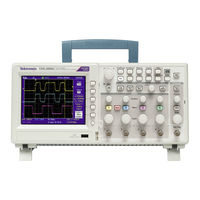
Tektronix TDS2024C User Manual (161 pages)
TDS2000C & TDS1000C-EDU Series Digital Storage Oscilloscopes
Brand:
Tektronix
| Category:
Test Equipment
| Size: 2.97 MB
Table of Contents
Table of Contents
9
General Safety Summary
12
Compliance Information
15
EMC Compliance
15
Safety Compliance
17
Environmental Considerations
19
Preface
21
Help System
22
Firmware Updates through the Internet
23
Conventions
24
Getting Started
25
General Features
25
Installation
26
Functional Check
28
Probe Safety
29
Voltage Probe Check Wizard
29
Manual Probe Compensation
31
Probe Attenuation Setting
31
Current Probe Scaling
32
Self Calibration
32
Operating Basics
33
Display Area
33
Using the Menu System
36
Vertical Controls
37
Horizontal Controls
38
Trigger Controls
39
Menu and Control Buttons
39
Input Connectors
42
Other Front-Panel Items
42
Understanding Oscilloscope Functions
43
Setting up the Oscilloscope
43
Triggering
44
Acquiring Signals
46
Scaling and Positioning Waveforms
47
Taking Measurements
49
Application Examples
53
Taking Simple Measurements
54
Using Autorange to Examine a Series of Test Points
59
Taking Cursor Measurements
60
Analyzing Signal Detail
64
Capturing a Single-Shot Signal
65
Measuring Propagation Delay
67
Triggering on a SpecifiC Pulse Width
68
Triggering on a Video Signal
69
Analyzing a Differential Communication Signal
73
Viewing Impedance Changes in a Network
74
Data Logging (Not Available on TDS1000C-EDU Models)
76
Limit Testing (Not Available on TDS1000C-EDU Models)
77
Math FFT
79
Setting up the Time-Domain Waveform
79
Displaying the FFT Spectrum
81
Selecting an FFT Window
82
Magnifying and Positioning an FFT Spectrum
85
Measuring an FFT Spectrum Using Cursors
86
USB Flash Drive and Device Ports
87
USB Flash Drive Port
87
File Management Conventions
88
Saving and Recalling Files with a USB Flash Drive
89
Using the Save Function of the Print Front Panel Button
91
USB Device Port
93
Installing the PC Communications Software on a PC
94
Connecting to a PC
94
Connecting to a GPIB System
96
Command Entry
96
Connecting to a Printer
97
Printing a Screen Image
97
Reference
99
Acquire
99
Autorange
101
Autoset
103
Cursor
106
Default Setup
107
Display
107
Help
110
Horizontal
110
Math
111
Measure
113
Print
114
Probe Check
115
Reference Menu
115
Save/Recall
115
Trigger Controls
120
Utility
125
Vertical Controls
128
Appendix A:specifications
131
Oscilloscope Specifications
131
Power Source
137
Appendix A: Specifications
131
Appendix B: TPP0101 and TPP0201 Series 10X Passive Probes Information
139
Connecting the Probe to the Oscilloscope
139
Compensating the Probe
139
Connecting the Probe to the Circuit
140
Standard Accessories
141
Optional Accessories
142
Specifications
142
Performance Graphs
143
Safety Summary
144
Appendix C: Accessories
147
Appendix D: Cleaning
149
General Care
149
Cleaning
149
Appendix E: Default Setup
151
Appendix F: Font Licenses
153
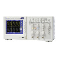
Tektronix TDS2024C Service Manual (114 pages)
TDS2000C Series; TDS1000C-EDU Series Digital Storage Oscilloscopes
Brand:
Tektronix
| Category:
Oscilloscope
| Size: 7.53 MB
Table of Contents
Table of Contents
3
General Safety Summary
8
Service Safety Summary
10
Preface
11
Manual Conventions
11
Related Documentation
11
Specifications
13
Signal Acquisition System Characteristics
13
Table 1: Signal Acquisition System Characteristics
13
Time Base System
19
Table 2: Time Base System
19
Triggering System
21
Table 3: Triggering System
21
Display Specifications
25
Table 4: Display Specifications
25
Interfaces and Output Ports Specifications
26
Data Handling Characteristics
26
Power Distribution System
26
Table 5: Interfaces and Output Ports Specifications
26
Table 6: Data Handling Characteristics
26
Table 7: Power Distribution System
26
Mechanical Characteristics
27
Environmental Performance
27
Data Logging System Characteristics (Not Available on TDS1000C-EDU Models)
27
Table 8: Mechanical Characteristics
27
Table 9: Environmental Performance
27
Limit Testing System Characteristics (Not Available on TDS1000C-EDU Models)
28
Table 10: Data Logging System Characteristics (Not Available on TDS1000C-EDU Models)
28
Table 11: Limit Testing System Characteristics (Not Available on TDS1000C-EDU Models)
28
Where to Find Operating Information
31
Theory of Operation
33
System Level Block Diagrams
34
Figure 1: Module-Level Block Diagram (2-Channel)
34
Figure 2: Module-Level Block Diagram (4-Channel)
35
Main Board
36
Acquisition System
36
Processing and Display System
37
Input Signal Interface
37
Probe Compensation
37
External Trigger
37
Main Board Power
37
Power Supply
37
Display Module
38
Front Panel
38
Two-Channel Oscilloscopes
38
Four-Channel Oscilloscopes
38
Performance Verification
39
Required Equipment
39
Table 12: Performance Verification
39
Test Record
40
Table 13: Test Record
40
Performance Verification Procedures
41
Self Test
41
Self Calibration
41
Check DC Gain Accuracy
41
Check Bandwidth
43
Check Sample Rate Accuracy and Delay Time Accuracy
44
Check Edge Trigger Sensitivity
45
Check External Edge Trigger Sensitivity
47
Check Vertical Position Accuracy
48
Figure 3: Example of a Line Graph for the Vertical Position Accuracy Test
51
Adjustment Procedures
53
Required Equipment
53
Adjustment Procedure
53
Table 14: Required Equipment
53
Enable the Service Menu
54
Figure 4: Adjustment Setups
55
Adjustment Procedure
56
Table 15: Adjustment Steps
57
Maintenance
61
Preventing ESD
61
Inspection and Cleaning
61
General Care
62
Interior Cleaning
62
Exterior Cleaning
62
Exterior Inspection
63
Interior Inspection
63
Table 16: External Inspection Checklist
63
Cleaning Procedure, Interior
64
Table 17: Internal Inspection Checklist
64
Removal and Installation Procedures
66
Summary of Procedures
66
Figure 5: Locator for Trim and Cabinet Removal (4-Channel Model Shown)
67
Figure 6: Locator for Internal Modules (4-Channel Model Shown)
67
Required Tools
68
Rear Feet
68
Flip Feet
69
Front-Panel Knobs
69
Power Button
69
Rear Case
70
Front Feet
71
Power Supply Module
72
Internal Assembly
73
Front-Panel Cable
74
Main Board Module (Serial Number C030000 or Later)
75
Figure 7: Instrument Cable Locations (Main Board SN C030000 or Later)
76
Display Module
78
Front-Panel Module
79
Keypad
80
Troubleshooting
81
Adjustment after Repair
81
Required Tools and Equipment
81
Troubleshooting Tree
81
Table 18: Tools and Equipment
81
Figure 8: Oscilloscope Troubleshooting Tree
82
Figure 9: Oscilloscope Troubleshooting Tree
83
Figure 10: Oscilloscope Troubleshooting Tree
84
Probe Comp Output
86
Table 19: Probe Comp Output
86
Troubleshooting the Power Supply
87
Table 20: Troubleshooting the Power Supply
87
Troubleshooting the Display
88
Troubleshooting the Front Panel
89
Table 21: Troubleshooting the Front Panel - Service
89
Table 22: Troubleshooting the Front Panel - Service Diag
89
Table 23: Troubleshooting the Front Panel - Mfg. Test
89
Table 24: Expected Signals at J202
90
Troubleshooting the Main Board
92
Table 25: Troubleshooting the Main Board
92
Table 26: List of Error Codes
93
Repackaging Instructions
95
Diagrams
97
Figure 11: TDS2000C and TDS1000C-EDU Series Block Diagram
98
Replaceable Parts
99
Parts Ordering Information
99
Using the Replaceable Parts List
100
Table 27: Replaceable Parts List
100
Parts Lists and Exploded Views
101
Figure 12: Exploded Diagram, 2-Channel Models
101
Table 28: Replaceable Parts List, 2-Channel Models
102
Figure 13: Exploded Diagram, 4-Channel Models
104
Table 29: Replaceable Parts List, 4-Channel Models
105
Figure 14: Power Supply Module, Cables, and Wires
106
Table 30: Replaceable Parts List; Power Supply Module, Instrument Cables, and Wires
106
Figure 15: Exploded Diagram, Back Case and Trim
108
Table 31: Replaceable Parts List, Back Case and Trim
109
Appendix A: Example of a Vertical Position Accuracy Test Spreadsheet
111
Sample Filled-In Vertical Position Accuracy Test Spreadsheet
111
Table 32: Vertical Position Accuracy Test Spreadsheet
111
Advertisement
Tektronix TDS2024C Security Instructions (20 pages)
Digital Storage Oscilloscope TBS1000, TBS1000B/TBS1000B-EDU, TDS1000B/TDS2000B, TDS1000C-EDU/TDS2000C, and TPS2000B Series
Brand:
Tektronix
| Category:
Test Equipment
| Size: 0.36 MB
Table of Contents
Table of Contents
5
Preface
7
Memory Devices
11
Volatile Memory Devices
11
Volatile Memory Devices (TBS1000B & TBS1000B-EDU)
13
Nonvolatile Memory Devices
14
Nonvolatile Memory Devices Container (TBS1000B & TBS1000B-EDU)
15
Data Export Devices
16
Clear and Sanitize Procedures
17
Clear the Flash Memory
17
Clear or Sanitize a Non-Functional Instrument
19
Acquisition Board
19
Compact Flash Card (TPS Oscilloscopes Only)
19
USB Flash Drive (TBS and TDS Oscilloscopes Only)
19
Charges
19
Tektronix TDS2024C Security Instructions (20 pages)
TBS1000, TBS1000B/TBS1000B-EDU, TDS1000B/TDS2000B, TDS1000C-EDU/TDS2000C, and TPS2000B Series Digital Storage Oscilloscope
Brand:
Tektronix
| Category:
Oscilloscope
| Size: 0.31 MB
Table of Contents
Table of Contents
5
Preface
7
Memory Devices
11
Volatile Memory Devices
11
Volatile Memory Devices (TBS1000B & TBS1000B-EDU)
13
Nonvolatile Memory Devices
14
Nonvolatile Memory Devices Container (TBS1000B & TBS1000B-EDU)
15
Data Export Devices
16
Clear and Sanitize Procedures
17
Clear the Flash Memory
17
Clear or Sanitize a Non-Functional Instrument
19
Acquisition Board
19
Compact Flash Card (TPS Oscilloscopes Only)
19
USB Flash Drive (TBS and TDS Oscilloscopes Only)
19
Charges
19
Tektronix TDS2024C Security Instructions (15 pages)
Digital Storage Oscilloscope TDS1000B Series TDS2000B Series TDS1000C-EDU Series TDS2000C Series TPS2000B Series
Brand:
Tektronix
| Category:
Test Equipment
| Size: 0.21 MB
Table of Contents
Table of Contents
3
Preface
5
Clear and Sanitize Procedures
9
Memory Devices
10
Data Export Devices
13
Troubleshooting
15
How to Clear or Sanitize a Nonfunctional Instrument
15
Advertisement
Related Products
Tektronix TDS2022C
Tektronix TDS2022B
Tektronix TDS2024B
Tektronix TDS2022
Tektronix TDS2024
Tektronix TDS2001C
Tektronix TDS2004C
Tektronix TDS2002
Tektronix TDS2012
Tektronix TDS2004
Tektronix Categories
Test Equipment
Measuring Instruments
Amplifier
Portable Generator
Printer
More Tektronix Manuals
Login
Sign In
OR
Sign in with Facebook
Sign in with Google
Upload manual
Upload from disk
Upload from URL