Sign In
Upload
Manuals
Brands
Tektronix Manuals
Measuring Instruments
TCP303
Tektronix TCP303 Manuals
Manuals and User Guides for Tektronix TCP303. We have
4
Tektronix TCP303 manuals available for free PDF download: Instruction Manual, Service Manual, User Manual, Safety Instructions
Tektronix TCP303 Instruction Manual (205 pages)
Amplifiers & AC/DC Current Probes
Brand:
Tektronix
| Category:
Amplifier
| Size: 2.45 MB
Table of Contents
Table of Contents
5
List of Tables
13
Preface
19
Getting Started
21
System Configuration
23
Figure 1- 1: Typical TCPA300/400 Current Measurement System
23
Options
25
Table 1- 1: Amplifier Options
25
Table 1- 2: Service Options
25
Standard Accessories
26
Optional Accessories
27
Probe Covers
28
Travel Case
29
Figure 1- 3: Equipment Locations in the Travel Case
29
Connecting the Amplifier to an Oscilloscope
30
Power on the Amplifier
30
Connecting a Current Probe to the Amplifier
31
Figure 1- 4: Connecting and Disconnecting a Current Probe to the Amplifier
31
Operating the Current Probe Slide
32
Figure 1- 5: TCP312 and TCP305 Slide Operation
32
Degaussing and Autobalancing the Current Probe
33
Figure 1- 6: TCP303 and TCP404XL Slide Operation
33
DC Measurements
34
Figure 1- 7: Current Probe Polarity
35
AC Measurements
36
Operating Basics
37
Control Summary
39
Figure 2- 1: the TCPA300 Front Panel
39
TCPA300 and TCPA400 Controls
40
PROBE DEGAUSS AUTOBALANCE Button and Indicator
40
MANUAL BALANCE Buttons and Indicator
41
PROBE OPEN Indicator
42
NOT TERMINATED into 50 Ω Indicator
42
NONCOMPATIBLE PROBE TYPE Indicator
42
ON/STANDBY Button
42
RANGE Button (TCPA300 Only)
42
COUPLING Button and Indicators
42
PROBE INPUT Connector
43
OUTPUT Connector
43
Probe DC Gain Adjust (Located on Probes)
43
GPIB Operation
44
Reference
45
Reference Notes
47
Degaussing a Probe with an Unpowered Conductor in the Jaws
47
Table 3- 1: Unpowered Circuit Degauss Limits
47
Measuring Differential Current
48
AC and DC Coupling
49
Figure 3- 1: Measuring Differential Current and Nulls
49
Maximum Current Limits
50
Figure 3- 3: Applying the Amp-Second Product Rule
51
Measuring Noncontinuous Current with the TCP404XL Probe
52
Figure 3- 4: Duty Cycle Calculation
52
Extending Current Range
54
Figure 3- 5: Increasing the DC Measurement Range
55
Increasing Sensitivity
56
Figure 3- 6: Increasing Probe Sensitivity
56
Application Notes
57
Automobile Charging Systems
57
Table 3- 2: Automobile Charging Systems Test Setup
57
Figure 3- 7: Setup for Measuring Charging Current
58
Figure 3- 8: Charge Current Waveforms
58
Inductance Measurements
59
Figure 3- 9: Measuring Inductance with a Low-Impedance Source
59
Figure 3- 10: Linear Current Vs. Time Ramp
60
Continuity Test of Multiple-Conductor Cable
61
Figure 3- 12: High-Impedance Source Current Ramp
61
Measuring Inductor Turns Count
62
Figure 3- 13: Measuring the Number of Turns in a Coil
62
Power Measurement and Analysis Software
63
Figure 3- 14: Turns Measurement Using Reference Coil
63
Troubleshooting and Error Codes
65
Table 3- 3: Troubleshooting
65
Displaying Error Codes with the Probe Degauss Autobalance Button
68
Figure 3- 15: Error Code Display
68
Figure 3- 16: Interpreting the Error Code Display
69
Table 3- 4: Amplifier Error Codes
69
Correcting the Cause of an Error Code
70
Shutdown Error
70
Specifications
71
Warranted Specifications
73
Table 4- 1: Warranted TCPA300 and TCPA400 Specifications
73
Nominal and Typical Characteristics
74
Table 4- 2: Nominal and Typical Amplifier Characteristics
74
Mechanical Characteristics
75
Table 4- 3: TCPA300 and TCPA400 Mechanical Characteristics
75
Figure 4- 1: Probe Jaw Dimensions (Nominal)
76
Table 4- 4: Probe Mechanical Characteristics
76
Table 4- 5: Shipping Weights and Dimensions
76
Environmental Characteristics
77
Table 4- 6: Environmental Characteristics
77
Table 4- 7: Certifications and Compliances
78
Figure 4- 2: Frequency Derating- TCP312
80
Figure 4- 3: Frequency Derating- TCP305
80
Figure 4- 4: Frequency Derating- TCP303
81
Figure 4- 5: Frequency Derating- TCP404XL
81
Figure 4- 6: Insertion Impedance Graphs for the Current Probes
82
Figure 4- 7: Specified Operating Area of the Probes
83
TCP404XL Maximum Measurement Times
84
Performance Verification
89
Performance Verification Overview
91
Performance Verification and Functional Checks
91
Table 5- 1: Amplifier Checks
91
Table 5- 2: Probe Performance Verification Checks
91
Test Procedure Conditions
92
Equipment Preparation
92
TCPA300 and TCPA400 Performance Verification
93
Equipment Required
93
Table 5- 3: Required Test Equipment
93
Making DC Current Loops
94
Front-Panel Display
95
DC Gain Accuracy
96
Table 5- 4: Equipment Settings
97
Bandwidth
99
Table 5- 6: Equipment Settings for Bandwidth Check
99
Table 5- 7: TCPA300 Bandwidth Measurements
101
Table 5- 8: TCPA400 Bandwidth Measurements
101
AC Coupling
102
Degauss
103
Current Overload Test
104
Table 5- 10: Maximum Current Ratings for TCPA300-Compatible Probes
105
TCPA300 Amplifier Test Record
106
TCPA400 Amplifier Test Record
107
TCP305 and TCP312 Performance Verification
109
Required Test Equipment
110
Table 5- 11: Required Test Equipment
110
DC Gain Accuracy
111
Table 5- 12: Equipment Settings for DC Gain Accuracy
111
Table 5- 13: DC Gain Accuracy Test for the TCP305 and TCP312
113
Rise Time
114
Table 5- 14: Equipment Settings for Rise Time
115
Bandwidth
116
Table 5- 15: Equipment Settings for Bandwidth
117
Table 5- 16: Bandwidth Test for the TCP305 and TCP312
118
TCP305 Current Probe Test Record
119
TCP312 Current Probe Test Record
120
TCP303 and TCP404XL Performance Verification
121
Equipment Required
122
Table 5- 17: Required Test Equipment
122
DC Gain Accuracy
123
Table 5- 18: Equipment Settings for DC Gain Accuracy
123
Rise Time
126
Bandwidth (TCP303)
129
Bandwidth (TCP404XL)
131
TCP303 Current Probe Test Record
132
TCP404XL Current Probe Test Record
133
Adjustment Procedures
135
Adjustment Procedures Overview
137
TCPA300 and TCPA400 Amplifier Adjustments
139
Required Test Equipment
139
Accessing the Adjustments
139
TCPA300 Amplifier
140
TCPA400 Amplifier
141
TCP305 and TCP312 Adjustments
143
Required Test Equipment
143
Accessing the Adjustments
143
TCP305 and TCP312 DC Gain Adjustment
144
TCP303 and TCP404XL Adjustments
147
Required Test Equipment
147
Adjustment Locations
148
TCP303 and TCP404XL Transient Response and Coarse Gain Adjustment
149
DC Gain Adjustment
154
Maintenance
157
Customer Maintenance
159
Service Strategy
159
Preventive Maintenance
159
Disassembly
161
Amplifiers
161
Equipment Required
161
Removing the Outer Case and Internal Covers
162
Replacing the Front Panel Assembly
165
Replacing the Amplifier Board
166
Replacing the Power Supply
168
Replacing the Fan
169
Probes 7
170
Probes
171
Equipment Required
171
TCP305 and TCP312
172
TCP303 and TCP404XL
176
Isolating Hardware Faults
179
Determining the Amplifier Firmware Version Number
180
Replaceable Parts
181
Parts Ordering Information
183
Using the Replaceable Parts List
183
Amplifier Replaceable Parts
185
Current Probes Replaceable Parts
191
Advertisement
Tektronix TCP303 Service Manual (120 pages)
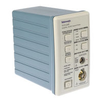
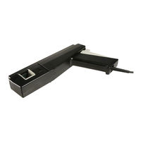
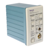
TCPA300 Series; TCPA400 Series AC/DC Current Probes
Brand:
Tektronix
| Category:
Measuring Instruments
| Size: 2.35 MB
Table of Contents
Service Manual
3
Table of Contents
7
General Safety Summary
13
Service Safety Summary
16
Compliance Information
17
EMC Compliance
17
Environmental Considerations
19
Preface
21
Manual Conventions
21
Performance Verification Overview
23
Performance Verification and Functional Checks
23
Table 1: Amplifier Checks
23
Table 2: Probe Performance Verification Checks
23
Test Procedure Conditions
24
Equipment Preparation
24
TCPA300 and TCPA400 Performance Verification
25
Equipment Required
25
Table 3: Required Test Equipment
25
Making DC Current Loops
26
Front-Panel Display
27
Figure 1: Check LED Functionality
27
DC Gain Accuracy
28
Figure 2: Equipment Setup for DC Gain Accuracy Test
28
Table 4: Equipment Settings
29
Table 5: DC Gain Accuracy Test for the TCPA300 and TCPA400
29
Bandwidth
31
Figure 3: Bandwidth Test Setup
31
Table 6: Equipment Settings for Bandwidth Check
31
Table 7: TCPA300 Bandwidth Measurements
34
Table 8: TCPA400 Bandwidth Measurements
34
AC Coupling
35
Figure 4: AC Coupling Test Setup
35
Degauss
36
Figure 5: Setup for Degaussing the Current Probe
36
Table 9: TCPA300 and TCPA400 AC Coupling Measurements
36
Current Overload Test (TCPA300 Only)
37
Figure 6: Overload Test Setup
37
Table 10: Maximum Current Ratings for TCPA300-Compatible Probes
38
TCPA300 Amplifier Test Record
39
TCPA400 Test Record
40
TCP305 and TCP312 Performance Verification
41
Required Test Equipment
42
Table 11: Required Test Equipment
42
DC Gain Accuracy
43
Figure 7: DC Gain Accuracy Test Setup for TCP305 and TCP312
43
Table 12: Equipment Settings for DC Gain Accuracy
44
Table 13: DC Gain Accuracy Test for the TCP305 and TCP312
45
Rise Time
46
Figure 8: Rise Time Test Setup for the TCP305 and TCP312
46
Table 14: Equipment Settings for Rise Time
47
Bandwidth
48
Figure 9: Bandwidth Test Setup for TCP305 and TCP312
48
Table 15: Equipment Settings for Bandwidth
49
Table 16: Bandwidth Test for the TCP305 and TCP312
50
TCP305 Current Probe Test Record
51
TCP312 Current Probe Test Record
52
TCP303 and TCP404XL Performance Verification
53
Equipment Required
54
Table 17: Required Test Equipment
54
DC Gain Accuracy
55
Figure 10: DC Gain Accuracy Test Setup for the TCP303 and TCP404XL
55
Table 18: Equipment Settings for DC Gain Accuracy
55
Table 19: DC Gain Accuracy Test Worksheet for the TCP303 and TCP404XL
57
Rise Time
58
Figure 11: Rise Time Test Setup for the TCP303 and TCP404XL
58
Table 20: Equipment Settings for Rise Time
59
Bandwidth (TCP303)
61
Figure 12: Bandwidth Test Setup for TCP303
61
Table 21: Equipment Settings for Bandwidth
62
Bandwidth (TCP404XL)
63
Table 22: Bandwidth Test for the TCP303
63
TCP303 Current Probe Test Record
64
TCP404XL Current Probe Test Record
65
Adjustment Procedures Overview
67
Table 23: Amplifier and Probe Adjustments
67
TCPA300 and TCPA400 Amplifier Adjustments
68
Required Test Equipment
68
Accessing the Adjustments
68
Table 24: Required Test Equipment
68
TCPA300 Amplifier
69
Figure 13: Amplifier Adjustments
69
Table 25: TCPA300 Gain Adjustments
69
TCPA400 Amplifier
70
Figure 14: Gain Adjustment Locations
70
Table 26: TCPA400 Gain Adjustments
70
TCP305 and TCP312 Adjustments
71
Required Test Equipment
71
Accessing the Adjustments
71
Figure 15: TCP305 and TCP312 DC Gain Adjustment Location
71
Table 27: Required Test Equipment
71
TCP305 and TCP312 DC Gain Adjustment
72
Table 28: Settings for DC Gain Adjustment
72
Figure 16: DC Gain Adjustment Setup for TCP305 and TCP312
73
Table 29: DC Gain Accuracy Adjustments for the TCP305 and TCP312
73
TCP303 and TCP404XL Adjustments
74
Required Test Equipment
74
Table 30: Required Test Equipment
74
Adjustment Locations
75
TCP303 and TCP404XL Transient Response and Coarse Gain Adjustment
75
Figure 17: TCP303 and TCP404XL Adjustment Locations
75
Figure 18: TCP303 and TCP404XL Transient Response and Coarse Gain Adjustment Setup
76
Table 31: Settings for Transient Response and Preliminary Gain Adjustments
77
DC Gain Adjustment
80
Figure 19: DC Gain Accuracy Adjustment Setup
80
Table 32: Equipment Settings for DC Gain Accuracy
81
Table 33: DC Gain Accuracy Adjustments for the TCP303 and TCP404XL
81
Maintenance
83
Service Strategy
83
Preventive Maintenance
83
Disassembly
84
Amplifiers
84
Equipment Required
84
Table 34: Equipment Required
84
Removing the Outer Case and Internal Covers
85
Figure 20: Removing the Case from the Amplifier
85
Figure 21: Removing the Right-Side Inner Panel
86
Figure 22: Removing the Left-Side Inner Panel
87
Replacing the Front Panel Assembly
88
Figure 23: Disconnecting the Front-Panel Assembly
88
Replacing the Amplifier Board
89
Figure 24: Removing the Three Heat Sink Clips
89
Figure 25: Removing the Amplifier Board
90
Replacing the Power Supply
91
Figure 26: Replacing the Power Supply
91
Replacing the Fan
92
Figure 27: Removing the AC Power Connector
92
Figure 28: Removing the Fan
93
Probes
94
Equipment Required
94
Table 35: Equipment Required
94
TCP305 and TCP312
95
Figure 29: Removing the Strain Relief Boot
95
Figure 30: Removing the Top Half of the Probe
96
Figure 31: Removing the Probe Slide
96
Figure 32: Removing the Current Transformer
97
Figure 33: Removing the Circuit Board and Cable Assembly
98
TCP303 and TCP404XL
99
Figure 34: Removing the Handle
99
Figure 35: Removing the Current Transformer
100
Figure 36: Removing the Circuit Board and Cable
101
Isolating Hardware Faults
102
Table 36: Amplifier Hardware Faults
102
Table 37: Probe Hardware Faults
102
Determining the Amplifier Firmware Version Number
103
Figure 37: Displaying the Amplifier Firmware Version Number
103
Replaceable Parts
105
Parts Ordering Information
105
Using the Replaceable Parts List
105
Amplifier Replaceable Parts
106
Figure 38: TCPA300 and TCPA400 Replaceable Parts
106
Table 38: TCPA300 and TCPA400 Replaceable Parts List
107
Table 39: Power Cord Identification
108
Figure 39: TCPA300 and TCPA400 Standard Accessories
109
Figure 40: TCPA300 and TCPA400 Optional Accessories
110
Current Probes Replaceable Parts
111
Table 42: TCP305 and TCP312 Replaceable Parts List
112
Figure 42: TCP303 Replaceable Parts
113
Table 43: TCP303 Replaceable Parts List
114
Figure 43: TCP404XL Replaceable Parts
115
Table 44: TCP404XL Replaceable Parts List
116
Tektronix TCP303 User Manual (80 pages)
Amplifiers & AC/DC Current Probes
Brand:
Tektronix
| Category:
Amplifier
| Size: 1.61 MB
Table of Contents
Table of Contents
7
General Safety Summary
11
Compliance Information
13
EMC Compliance
13
Environmental Considerations
15
Preface
17
Manual Conventions
17
Getting Started
19
Figure 1: Typical TCPA300/400 Current Measurement System
19
System Configuration
19
Options
21
Table 1: Amplifier Options
21
Table 2: Service Options
21
Optional Accessories
22
Standard Accessories
22
Figure 2: Using the Probe Covers
23
Probe Covers
23
Figure 3: Equipment Locations in the Travel Case
24
Travel Case
24
Connecting the Amplifier to an Oscilloscope
25
Power on the Amplifier
25
Connecting a Current Probe to the Amplifier
26
Figure 4: Connecting and Disconnecting a Current Probe to the Amplifier
26
Figure 5: TCP312 and TCP305 Slide Operation
27
Operating the Current Probe Slide
27
Figure 6: Unlock and Open the TCP303 and TCP404XL
28
Figure 7: Close and Lock the TCP303 and TCP404XL
28
Degaussing and Autobalancing the Current Probe
29
DC Measurements
30
Figure 8: Current Probe Polarity
31
AC Measurements
32
Figure 9: the TCPA300 Front Panel
33
TCPA300 and TCPA400 Controls
34
Control Summary
33
Reference Notes
39
Degaussing a Probe with an Unpowered Conductor in the Jaws
39
Table 3: Unpowered Circuit Degauss Limits
39
Measuring Differential Current
40
Figure 10: Measuring Two Conductors
40
Figure 11: Measuring Differential Current and Nulls
41
AC and DC Coupling
42
Figure 12: Effect of AC or DC Coupling on Low-Frequency Signals
42
Maximum Current Limits
43
Figure 13: Applying the Amp-Second Product Rule
44
Measuring Noncontinuous Current with the TCP404XL Probe
46
Figure 14: Duty Cycle Calculation
46
Extending Current Range
48
Figure 15: Adding a Second Conductor
48
Figure 16: Adding Multiple Turns
49
Increasing Sensitivity
50
Figure 17: Increasing Probe Sensitivity
50
Application Notes
51
Automobile Charging Systems
51
Table 4: Automobile Charging Systems Test Setup
51
Figure 18: Setup for Measuring Charging Current
52
Figure 19: Charge Current Waveforms
52
Figure 20: Measuring Inductance with a Low-Impedance Source
53
Inductance Measurements
53
Figure 21: Linear Current Vs. Time Ramp
54
Continuity Test of Multiple-Conductor Cable
55
Figure 22: High-Impedance Source Current Ramp
55
Figure 23: Measuring the Number of Turns in a Coil
56
Figure 24: Turns Measurement Using Reference Coil
56
Measuring Inductor Turns Count
56
Power Measurement and Analysis Software
57
Table 5: Troubleshooting
58
Displaying Error Codes with the Probe Degauss Autobalance Button
61
Figure 25: Error Code Display
61
Figure 26: Interpreting the Error Code Display
62
Table 6: Amplifier Error Codes
62
Correcting the Cause of an Error Code
63
Shutdown Error
63
Troubleshooting and Error Codes
58
Specifications
65
Warranted Specifications
65
Table 7: Warranted TCPA300 and TCPA400 Specifications
65
Nominal and Typical Characteristics
66
Table 8: Nominal and Typical Amplifier Characteristics
66
Mechanical Characteristics
67
Table 9: TCPA300 and TCPA400 Mechanical Characteristics
67
Figure 27: Probe Jaw Dimensions (Nominal)
68
Table 10: Probe Mechanical Characteristics
68
Table 11: Shipping Weights and Dimensions
68
Environmental Characteristics
69
Table 12: Environmental Characteristics
69
Performance Graphs
70
Figure 28: Frequency Derating-TCP312
70
Figure 29: Frequency Derating-TCP305
70
Figure 30: Frequency Derating-TCP303
70
Figure 31: Frequency Derating-TCP404XL
71
Figure 32: Insertion Impedance Versus Frequency
72
Figure 33: Specified Operating Area of the Probes
73
TCP404XL Maximum Measurement Times
74
Figure 34: Measuring 750A Noncontinuous at 50 °C Ambient Temperature
74
Figure 35: Measuring 600A Noncontinuous at 50 °C Ambient Temperature
74
Safety Compliance Information
75
Figure 36: Measuring 750A Noncontinuous at 23 °C Ambient Temperature
75
Table 13: Safety Compliance Information
75
Glossary
77
Advertisement
Tektronix TCP303 Safety Instructions (32 pages)
Amplifiers and Current Probes
Brand:
Tektronix
| Category:
Amplifier
| Size: 0.52 MB
Table of Contents
Table of Contents
3
Important Safety Information
5
General Safety Summary
5
Service Safety Summary
8
Terms in this Manual
8
Symbols and Terms on the Product
9
Compliance Information
10
EMC Compliance (TCPA300/400 Only)
10
Safety Compliance
11
Environmental Considerations
13
Operating Considerations
14
Installation
16
Standard Accessories
16
Optional Accessories
17
System Configuration
17
Connect the Amplifier to an Oscilloscope
18
Power on the Amplifier
19
Connect the Probe to the Amplifier
20
Operate the Amplifier
21
LED Indicators
22
Overload Conditions
23
Operate the Current Probe
24
Basic Operation
24
Operate the Current Probe Slide
25
Degauss and Autobalance the Current Probe
28
Use the Ground Lead
29
Make DC Current Measurements
30
Make AC Current Measurements
32
Advertisement
Related Products
Tektronix TCP312
Tektronix TCP305
Tektronix TCP0020
Tektronix TCP2020
Tektronix TCAL500
Tektronix TDP3500
Tektronix TLA6204
Tektronix TLA 714
Tektronix IsoVu TIVM1
Tektronix TRCP3000
Tektronix Categories
Test Equipment
Measuring Instruments
Amplifier
Portable Generator
Printer
More Tektronix Manuals
Login
Sign In
OR
Sign in with Facebook
Sign in with Google
Upload manual
Upload from disk
Upload from URL