Sign In
Upload
Manuals
Brands
Tektronix Manuals
Test Equipment
TAS 465
Tektronix TAS 465 Manuals
Manuals and User Guides for Tektronix TAS 465. We have
3
Tektronix TAS 465 manuals available for free PDF download: Service Manual, Instruction Manual
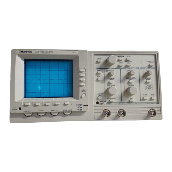
Tektronix TAS 465 Service Manual (268 pages)
Analog Oscilloscope
Brand:
Tektronix
| Category:
Test Equipment
| Size: 4.82 MB
Table of Contents
Table of Contents
3
List of Figures
9
List of Tables
13
Safety Summary
15
Symbols and Terms
15
Specific Precautions
16
Preface
19
Related Manuals
20
Product Description
21
User Interface
22
Autoset
22
Menus
22
General Purpose Knob and TOGGLE
22
Save/Recall Setups
22
Vertical System
23
Horizontal System
23
Trigger System
23
Measurement Cursors
23
Nominal Traits
25
Table 1 1: Nominal Traits
25
Table 1 2: Nominal Traits
26
Table 1 3: Nominal Traits
26
Table 1 4: Nominal Traits
26
Table 1 9: Nominal Traits Mechanical
28
Warranted Characteristics
29
Performance Conditions
29
Table 1 10: Warranted Characteristics
29
Typical Characteristics
35
Table 1 18: Typical Characteristics
35
Table 1 19: Typical Characteristics
35
Table 1 20: Typical Characteristics
36
Table 1 21: Typical Characteristics
37
Table 1 22: Typical Characteristics
37
Table 1 23: Typical Characteristics
37
Table 1 24: Typical Characteristics
37
Installation and Power on
39
Figure 2 1: Rear Panel
39
Figure 2 2: Fuse Compartment
40
Figure 2 3: POWER Button
40
Quick Start
41
Selecting and Deselecting Input Channels
41
Using the Menus
41
Connecting a Signal
42
Using AUTOSET
42
Compensating the Probe
43
Figure 2 4: Probe Compensation Signal Displayed after AUTOSET
43
Figure 2 5: Connections for Compensating a Probe
43
Figure 2 6: How Probe Compensation Affects Signals
45
Figure 2 7: Location of Probe Head Adjustment
45
Menu Map
46
Figure 2 8: Menu Map
46
Circuit Description
47
Logic Conventions
47
Module Interconnection
47
Figure 3 1: Block Diagram
48
Analog Board
50
Attenuators A1
50
Probe Coding Interface A1
50
Analog Acquisition Hybrid A1
50
External Trigger A1
50
Processor System
50
Processor Subsystem A5
50
ROM/RAM Subsystem A5
51
Readout Subsystem A5
51
Front Panel Interface Subsystem A5
51
Analog Board Interface Subsystem A5
51
Display Assembly
52
Vertical Output A3
52
Horizontal Output A3
52
High Voltage A3
52
Front Panel
52
Menu Switches A4
53
Cpu A4
53
FPP Pots & Probes A4
53
Leds & Driver A4
53
Switches A4
54
Power Supply
54
Fan
54
General Instructions
55
Using the Brief Performance Checks Procedures
55
Using the Performance Tests Procedures
55
Conventions
56
Figure 4 1: Graticule References
56
Brief Performance Checks
57
Power on Self Tests
57
Functional Tests
57
Functional Tests Prerequisites
58
Verify the Probe Compensator Output
58
Figure 4 2: Test Hookup for Functional Tests
58
Verify the Input Channels
59
Verify the Alt/Chop and Add Functions
60
Verify the Time Base
60
Verify the Trigger System
61
Verify the External Trigger
63
Temperature Compensation Calibrations
63
Horizontal Sweep Path
63
Figure 4 3: Horizontal Adjustments (One)
64
Figure 4 4: Horizontal Adjustments (Two)
64
Vertical Signal Path
65
Figure 4 5: Horizontal Adjustments (Three)
65
Performance Tests
67
Performance Tests Prerequisites
67
Equipment Required
67
Table 4 1: Required Test Equipment
68
Vertical System Checks
69
Check DC Gain and Voltage Measurement Accuracy
69
Figure 4 6: Gain and Voltage Test Setup
69
Check Trigger Level Accuracy
70
Table 4 2: DC Gain and Delta Volts Accuracy
70
Check DC Coupling Bandwidth
71
Figure 4 7: Trigger Level Test Setup
71
Figure 4 8: Bandwidth Test Setup
72
Table 4 3: DC Coupled Bandwidth
72
Check X Axis Gain
73
Figure 4 9: X Axis Gain Test Setup
73
Horizontal System Checks
74
Check Time Base and Time Cursor Accuracy
74
Figure 4 10: Timing Test Setup
74
Table 4 4: Time Base and Cursor Accuracies (Mag Off)
75
Check Dual Delay Accuracy
76
Table 4 5: Time Base Accuracy (Mag On)
76
Figure 4 11: Dual Delay Test Setup
77
Trigger System Checks
78
Check Trigger Sensitivity
78
Table 4 6: 500 Ms Dual Delay Accuracy
78
Figure 4 12: Trigger Sensitivity Test Setup (One)
79
Figure 4 13: Trigger Sensitivity Test Setup (Two)
80
Figure 4 14: Trigger Sensitivity Test Setup (Three)
81
Figure 4 15: Trigger Sensitivity Test Setup (Four)
81
Video Trigger Sensitivity
83
Figure 4 16: Video Trigger Test Setup
83
Adjustment Procedures
85
Requirements for Performance
85
Personnel
85
Access to Adjustments
85
Warm up Period
85
Equipment Required
86
Figure 5 1: Location of Boards for Adjustments
86
Performing the Adjustment Procedures
87
Complete Adjustment
87
Partial Adjustment
87
Adjustment Dependencies
87
Adjustment Instructions
88
Power Supply Adjustment
88
Table 5 1: Adjustments and Dependencies
88
CRT Adjustments
89
Figure 5 2: CRT Adjustments Calibration Setup
89
Low Frequency Output Compensation
90
Figure 5 3: Low Frequency Output Compensation Calibration
91
Factory Horizontal Cal
92
Figure 5 4: Horizontal Adjustments (One)
93
Figure 5 5: Horizontal Adjustments (Two)
93
Figure 5 6: Horizontal Adjustments (Three)
94
Figure 5 7: Horizontal Output Calibration Setup
95
Factory Vertical Cal
96
Figure 5 8: Factory Vertical Calibration Setup
97
Figure 5 9: External Trigger Calibration Setup
97
Figure 5 10: Vertical Adjustments
98
High Frequency Step Response
99
Figure 5 11: Adjusting Vertical Gain and Centering
99
Attenuator Compensation
100
Figure 5 12: High Frequency Step Response Test Setup
100
Figure 5 13: Attenuator Compensation Test Setup
101
Vertical Gain Adjust (Cabinet On)
102
Figure 5 14: Display Driver Board Adjustment Locations
104
Figure 5 15: Analog Board Adjustment Locations
105
Figure 5 16: Power Supply Adjustment Location
106
Figure 5 17: Location of J205 (CAL-DIS) on the CPU Board
107
Maintenance Information
109
Before Servicing
109
Tektronix Service
109
Warranty Service
109
Repair or Calibration Service
110
Self Service
110
Preventing ESD
110
Table 6 1: Relative Susceptibility to Static Discharge Damage
111
Inspection and Cleaning
113
General Care
113
Inspection and Cleaning Procedures
113
Inspection Exterior
114
Cleaning Procedure Exterior
114
Table 6 2: External Inspection Check List
114
Cleaning Procedure Interior
115
Cleaning the CRT Implosion Shield
115
Removal and Installation Procedures
117
Preparation Please Read
117
Cable Removal
117
General Instructions
118
Summary of Procedures
118
Figure 6 1: Oscilloscope Orientation
118
Table 6 3: Tools Required for Module Removal
119
Figure 6 2: Cabinet and Front Panel Mounted Modules
120
Figure 6 3: Internal Modules
121
Line Cord and Line Fuse
122
Line Cord
122
Figure 6 4: Cables and Cable Routing
122
Line Fuse
123
Front Panel Knobs and Shafts
123
Figure 6 5: Line Fuse and Line Cord Removal
123
Removing Front Panel Knobs and Shafts
124
Installing Front Panel Knobs and Shafts
124
Figure 6 6: Knob and Shaft Removal
124
Feet, Rear Cover, and Cabinet
125
Figure 6 7: Rear Cover, Cabinet, and Feet Removal
125
Rear Cover
126
Cabinet
126
Replacing the Front Feet
126
Front Panel Trim, Menu and Power Buttons, EMI Gasket
126
Removing the Front Trim
126
Menu Buttons and Elastomer
127
Power Button Replacement
127
Installing the Front Trim
127
Installing the EMI Gaskets
128
Figure 6 8: Trim Ring and Menu Buttons Removal
128
A62 Front Panel Module Removal
129
Figure 6 9: EMI Gasket Installation
129
Front Panel Module Disassembly/Assembly
130
Figure 6 10: A62 Front Panel Module Removal
130
Figure 6 11: Disassembly of Front Panel Assembly
131
Reassembly of the Front Panel Module
132
Figure 6 12: Front Panel Ground Spring
132
Menu Flex Circuit Replacement
133
Figure 6 13: Menu Flex Circuit Board Removal
133
A1 Analog Board
134
Display Driver Board (A3)
135
Figure 6 14: A1 Analog Board Removal
135
Figure 9 5: A1 Analog Board
135
CRT Implosion Shield
136
Figure 6 15: Location of Display Driver Board
136
Figure 6 16: CRT Implosion Shield Removal
137
Figure 6 17: Fan Mount Removal
138
Figure 6 18: Fan and Fan Mount Removal
139
Figure 6 19: CRT Rear Bracket and Ground Wire
141
Figure 6 20: CRT Removal
143
Figure 6 21: Removing the CRT Front Bracket
145
Figure 6 22: Removing the Display Control Board
146
Figure 6 23: Power Button Shaft Disconnect
147
Figure 6 24: Power Supply Removal
147
Table 6 4: Equipment Required for Troubleshooting
149
Table 6 5: Symptom Matrix
150
Figure 6 25: A5 CPU Board Troubleshooting Procedure
152
Figure 6 26: A1 Analog Board Troubleshooting Procedure
153
Figure 6 27: A3 Display Driver Board Troubleshooting Procedure
155
Figure 6 28: A62 Front Panel Module Troubleshooting Procedure
157
Figure 6 29: A2 Display Control Board Troubleshooting Procedure
158
Table 7 1: International Power Cords
161
Figure 9 1: Graphic Items and Special Symbols Used in this
194
Figure 9 2: Circuit Board Component Locator Diagram Key
194
Figure 9 3: Semiconductor Lead Configurations
195
Figure 9 4: Locating Components on Circuit Board or Schematic
196
Figure 9 6: A2 Display Control Board
201
Figure 9 7: A3 Display Driver Board
203
Figure 9 8: A4 Front Panel Board
205
Figure 9 9: A5 Processor Board
207
Figure 9 10: A63 Power Supply
209
Figure 10 1: Cabinet and Rear
261
Figure 10 2: Front Panel Assembly
263
Figure 10 3: Chassis
265
Figure 10 4: Circuit Boards
267
Figure 10 5: Accessories
268
Advertisement
Tektronix TAS 465 Service Manual (227 pages)
Analog Oscilloscope
Brand:
Tektronix
| Category:
Test Equipment
| Size: 3.24 MB
Table of Contents
Table of Contents
5
List of Figures
11
List of Tables
15
Safety Summary
17
Symbols
17
Specific Precautions
18
Product Description
24
User Interface
25
Autoset
25
Menus
25
Save/Recall Setups
25
Vertical System
26
Horizontal System
26
Trigger System
26
Measurement Cursors
26
Nominal Traits
28
Typical Characteristics
40
Installation and Power on
45
Fuse Compartment
46
Power Button
46
Quick Start
47
Selecting and Deselecting Input Channels
47
Using the Menus
47
Connecting a Signal
48
Using AUTOSET
48
Compensating the Probe
49
Connections for Compensating a Probe
49
How Probe Compensation Affects Signals
51
Location of Probe Head Adjustment
51
Menu Map
52
Circuit Description
54
Logic Conventions
54
Module Interconnection
54
Block Diagram
55
Analog Board
57
Attenuators
57
Probe Coding Interface
57
Processor System
57
Display Assembly
59
Front Panel
59
Vertical Output
59
Horizontal Output
59
Menu Switches
60
Cpu A4
60
FPP Pots and Probes A4
60
Leds and Driver A4
60
Power Supply
61
Fan
61
General Instructions
63
Using the Brief Performance Checks Procedures
63
Using the Performance Tests Procedures
63
Conventions
64
Graticule References
64
Brief Performance Checks
65
Power-On Self Tests
65
Functional Tests
65
Functional Tests Prerequisites
66
Verify the Probe Compensator Output
66
Verify the Input Channels
67
Verify the Alt/Chop and Add Functions
68
Verify the Time Base
68
Verify the Trigger System
69
Temperature Compensation Calibrations
71
Verify the External Trigger
71
Horizontal Sweep Path
71
Vertical Signal Path
73
Performance Tests
75
Performance Tests Prerequisites
75
Equipment Required
75
Vertical System Checks
77
Check DC Gain and Voltage Measurement Accuracy
77
Gain and Voltage Test Setup
77
Check Trigger Level Accuracy
78
DC Gain and Delta Volts Accuracy
78
Check DC Coupling Bandwidth
79
Trigger Level Test Setup
79
Bandwidth Test Setup
80
DC Coupled Bandwidth
80
Horizontal System Checks
81
Check X-Axis Gain
81
Check Time Base and Time Cursor Accuracy
81
Timing Test Setup
82
Time Base and Cursor Accuracies
82
Check Dual Delay Accuracy
84
Time Base Accuracy
84
Dual Delay Test Setup
85
Trigger System Checks
86
Check Trigger Sensitivity
86
Low Frequency
86
High Frequency
89
Video Trigger Sensitivity
90
Adjustment Procedures
94
Requirements for Performance
94
Personnel
94
Access to Adjustments
94
Performing the Adjustment Procedures
95
Location of Boards for Adjustments
95
Complete Adjustment
96
Partial Adjustment
96
Adjustment Dependencies
96
Power Supply Adjustment
97
New Style Power Supply
97
CRT Adjustments
97
CRT Adjustments Calibration Setup
98
Low Frequency Output Compensation
99
Factory Horizontal Cal
100
Factory Vertical Cal
104
External Trigger Calibration Setup
106
Vertical Adjustments
106
High Frequency Step Response
107
Adjusting Vertical Gain and Centering
107
High Frequency Step Response Test Setup
108
Attenuator Compensation
109
Attenuator Compensation Test Setup
109
Vertical Gain Adjust (Cabinet On)
110
Adjustment Complete
111
Display Driver Board Adjustment Locations
112
Analog Board Adjustment Locations
113
Power Supply Adjustment Location
114
Location of J205 on the CPU Board
115
Maintenance Information
117
Before Servicing
117
Tektronix Service
117
Repair or Calibration Service
118
Preventing ESD
118
Inspection and Cleaning
121
General Care
121
Inspection - Exterior
122
External Inspection Check List
122
Cleaning Procedure - Exterior
122
Cleaning - Interior
123
Cleaning the CRT Implosion Shield
123
Removal and Installation
125
Preparation
125
Cable Removal
125
Summary of Procedures
126
Oscilloscope Orientation
126
Tools Required for Module Removal
127
Cabinet and Front Panel Mounted Modules
128
Internal Modules
129
Line Cord and Line Fuse
130
Cables and Cable Routing
130
Front Panel Knobs and Shafts
131
Line Fuse
131
Removing Front Panel Knobs and Shafts
131
Installing Front Panel Knobs and Shafts
132
Knob and Shaft Removal
132
Feet, Rear Cover, and Cabinet
133
Rear Cover
134
Cabinet
134
Replacing the Front Feet
134
Removing the Front Trim
134
Menu Buttons and Elastomer
135
Power Button Replacement
135
Installing the Front Trim
135
A62 Front Panel Module Removal
136
Front Panel Module Disassembly/Assembly
137
A4 Front Panel Board Removal
137
Front Panel Buttons and Elastomer
138
Ground Spring Removal
138
Menu Flex Circuit Replacement
139
Reassembly of the Front Panel Module
139
A1 Analog Board
140
Menu Flex Circuit Board Removal
140
Display Driver Board
142
A1 Analog Board Removal
142
CRT Implosion Shield
143
Location of Display Driver Board
143
Current Method
143
CRT Implosion Shield Removal
144
Fan and Fan Mount
145
Early Method
145
Fan and Fan Mount Removal
145
Crt
147
Fan and Fan Mount Installation
147
CRT Removal
147
CRT Rear Bracket and Ground Wire
148
CRT Installation
149
CRT Light Guide
150
CRT Front Bracket
151
A2 Display Control Board
152
Removing the CRT Front Bracket
152
A63 Power Supply Module
153
Power Supply Removal
153
Removing the Display Control Board
153
Power Supply Installation
154
Power Button Shaft Disconnect
154
Troubleshooting
157
Equipment
157
Symptom Matrix
158
A5 CPU Board Troubleshooting
160
A1 Analog Board Troubleshooting
161
A3 Display Driver Board Troubleshooting
163
Repackaging Information
167
Options
170
International Power Cords
170
Rackmount
170
Front Cover and Pouch
171
Additional Probes
171
Replaceable Electrical Parts
173
Parts Ordering Information
173
List of Assemblies
173
Component Number
173
Serial No.
174
Name & Description
174
Mfr. Code
174
Mfr. Part No.
174
Cross Index
175
Diagrams and Circuit Board Illustrations
206
Component Values
206
Component Locator Diagrams
207
Graphic Items and Special Symbols
207
Circuit Board Component Locator Diagram Key
207
Replaceable Mechanical Parts
209
Using the Replaceable Parts List
209
Item Names
209
Indentation System
210
Abbreviations
210
Cabinet and Rear
213
Front Panel Assembly
215
Chassis
220
Circuit Boards
222
Table of Contents
227
Tektronix TAS 465 Instruction Manual (260 pages)
Analog Oscilloscopes
Brand:
Tektronix
| Category:
Test Equipment
| Size: 3.95 MB
Advertisement
Advertisement
Related Products
Tektronix TAS 250
Tektronix TAS 455
Tektronix TAS 475
Tektronix TAS 485
Tektronix TDS2012B
Tektronix TDS2014B
Tektronix TPS2024B
Tektronix TDS5054
Tektronix TDS3034
Tektronix TDS 714L
Tektronix Categories
Test Equipment
Measuring Instruments
Amplifier
Portable Generator
Printer
More Tektronix Manuals
Login
Sign In
OR
Sign in with Facebook
Sign in with Google
Upload manual
Upload from disk
Upload from URL