Sign In
Upload
Manuals
Brands
Tektronix Manuals
Inverter
AWG70002A
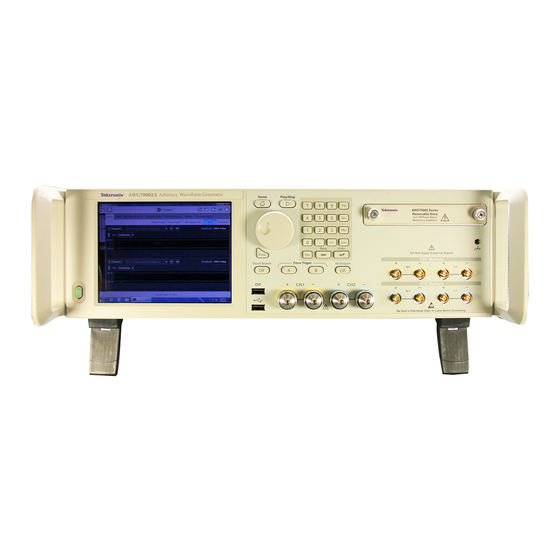
Tektronix AWG70002A Manuals
Manuals and User Guides for Tektronix AWG70002A. We have
2
Tektronix AWG70002A manuals available for free PDF download: Technical Reference, Installation And Safety Instructions
Tektronix AWG70002A Technical Reference (81 pages)
Arbitrary Waveform Generators and Synchronization Hub Specifications and Performance Verification
Brand:
Tektronix
| Category:
Portable Generator
| Size: 2.12 MB
Table of Contents
Table of Contents
5
General Safety Summary
9
Service Safety Summary
11
Preface
13
Related Documents
13
Specifications
15
Performance Conditions
17
Electrical Specifications
18
Table 1-1: Run Mode
18
Table 1-2: Arbitrary Waveform
18
Table 1-3: Sample Clock Generator
19
Table 1-4: Analog Output
19
Table 1-5: SFDR, AWG70001A & AWG70002A Operating at 25 Gs/S
22
Table 1-6: SFDR, AWG70001A Operating at 50 Gs/S
23
Table 1-7: SFDR, AWG70002A Operating at 8 Gs/S
23
Table 1-8: SFDR, AWG70002A Operating at 16 Gs/S
24
Table 1-9: Phase Noise with Jitter Reduction, AWG70001A Operating at 50 Gs/S
24
Table 1-10: Phase Noise with Jitter Reduction, AWG70001A & AWG70002A Operating at 25 Gs/S
24
Table 1-11: Phase Noise with Jitter Reduction, AWG70002A Operating at 8 Gs/S
25
Table 1-12: Phase Noise with Jitter Reduction, AWG70002A Operating at 16 Gs/S
25
Table 1-13: Phase Noise Without Jitter Reduction, AWG70001A Operating at 49.998998 Gs/S
25
Table 1-14: Phase Noise Without Jitter Reduction, AWG70001A & AWG70002A Operating at
25
Table 1-15: Phase Noise Without Jitter Reduction, AWG70002A Operating at 7.998997998 Gs/S
26
Table 1-16: Phase Noise Without Jitter Reduction, AWG70002A Operating at 15.998997998 Gs/S
26
Table 1-17: AC Analog Output (AWG70001A, Option AC)
26
Table 1-18: Marker Output
28
Table 1-19: Clock Output
29
Table 1-20: Clock Input
30
Table 1-21: Trigger Input
30
Table 1-22: Reference Clock Input
31
Table 1-23: Sync Clock Output
31
Table 1-24: Sequencer
32
Table 1-25: Pattern Jump in Connector
32
Table 1-26: Flag out Connectors
33
Table 1-27: 10 Mhz Reference Clock Output
33
Table 1-28: CPU Module and Peripheral Devices
34
Table 1-29: Display
34
Table 1-30: Power Supply
34
Mechanical Characteristics
35
Table 1-31: Mechanical Characteristics
35
Figure 1-1: Dimensions and Minimum Cooling Clearances
36
Environmental Characteristics
37
Table 1-32: Environmental Characteristics
37
Awgsync01
38
Electrical Specifications
38
Table 1-33: Electrical Specifications
38
Mechanical Characteristics
41
Table 1-34: Power Supply
41
Table 1-35: Mechanical Characteristics
41
Performance Verification
43
Performance Verification Procedures
45
Input and Output Options
46
Figure 2-1: Peripheral Connections
46
Instrument Interface Overview
47
Brief Procedures
51
Diagnostics
51
Figure 2-2: Diagnostics Dialog Box
51
Calibration
52
Figure 2-3: Calibration Dialog Box
52
Functional Test
53
Table 2-1: Required Equipment for the Functional Test
53
Table 2-2: Test Waveforms
53
Figure 2-4: Equipment Connections for Checking the Analog and Marker Outputs
54
Figure 2-5: Output Waveform from the Channel, Marker 1, and Marker 2 Connectors
56
Figure 2-6: Equipment Connections for Checking the AC Output
57
Figure 2-7: 1 Ghz Output Waveform - no Filter
59
Figure 2-8: 1 Ghz Output Waveform - Filter Set to Low Pass
60
Figure 2-9: 11 Ghz Output Waveform
61
Figure 2-10: 14 Ghz Output Waveform
62
Figure 2-11: Equipment Connection for Checking the Triggered Outputs
63
Performance Tests
65
Prerequisites
65
Required Equipment
65
Table 2-4: Performance Test Waveforms
66
10 Mhz Reference Frequency Accuracy
67
Figure 2-12: Equipment Connection for Verifying the 10 Mhz Reference Frequency Accuracy
67
Analog Amplitude Accuracy
68
Figure 2-13: Equipment Connection for Measuring the Termination Resistance
68
Figure 2-14: Equipment Connection for Checking the Analog Amplitude Accuracy
69
Table 2-5: Analog Amplitude Accuracy
70
Analog AC Amplitude Accuracy (Option AC Only)
72
Figure 2-15: Equipment Connection for Measuring the Termination Resistance
72
Figure 2-16: Equipment Connection for Checking the Analog Amplitude Accuracy
73
Marker High and Low Level Accuracy
75
Figure 2-17: Equipment Connection for Verifying the Marker High and Low Level Accuracy
75
Table 2-7: Marker High Level Accuracy
76
Table 2-8: Marker Low Level Accuracy
77
Test Record
79
Advertisement
Tektronix AWG70002A Installation And Safety Instructions (52 pages)
Arbitrary Waveform Generators
Brand:
Tektronix
| Category:
Inverter
| Size: 1.37 MB
Table of Contents
Table of Contents
7
Important Safety Information
9
General Safety Summary
9
Terms in the Manual
10
Terms on the Product
11
Symbols on the Product
11
Preface
13
Key Features
13
Documentation
13
Conventions Used in this Manual
14
Install the Instrument
15
Standard Accessories
15
Product Options
16
Product Upgrades
17
Replaceableparts
17
Operating Requirements
18
Environmental Requirements
18
Power Supply Requirements
18
Cleaning
18
Power on the Instrument
19
Power off the Instrument
20
Inspect the Instrument
20
Self Calibration
21
Connecting to the Instrument
22
Connecting to a Network
22
Connecting Peripheral Devices
23
Controlling the Instrument Using a Remote PC
23
Preventing Instrument Damage
23
Overheat Protection
23
Connectors
23
Options and Upgrades
24
View Installed Options
24
Install a New Option Key
25
Windows Interface Guidelines
25
Operating Basics
27
Front-Panel Connectors
27
Rear-Panel Connectors
29
Getting Acquainted with Your Instrument
30
Touchscreen Interface
30
Front-Panel Controls
30
AWG Mode General Overview
32
Functions Mode General Overview
34
Run State Control
35
Run Mode
36
Changing Control Settings
36
Preferences
37
Basic Guidelines to Play a Waveform
37
Restoring Instrument Operating System and Product Software
38
Operating System Restore
38
Internal Recovery Utility
38
AWG7000A Series Product Software and Tekvisa Installation
38
Specifications
39
General Characteristics
39
Sample Clock Generator Characteristics
40
Analog Output Characteristics
40
Analog AC Output (AWG70001A with Option AC)
41
Marker Outputs
42
Flag Outputs
42
Auxillary Outputs
43
Auxiliary Inputs
43
Computer Outputs
44
Power Characteristics
44
EMC, Environment, and Safety
44
Compliance Information
45
EMC Compliance
45
Safety Compliance
46
Environmental Compliance
47
Advertisement
Related Products
Tektronix AWG710
Tektronix AWG710B
Tektronix AWG70001A
Tektronix AWG7000 Series
Tektronix AWG5000 Series
Tektronix AWG5200 Series
Tektronix AFG3011C
Tektronix AFG1022
Tektronix AFG1062
Tektronix AFG31022GSA
Tektronix Categories
Test Equipment
Measuring Instruments
Amplifier
Portable Generator
Printer
More Tektronix Manuals
Login
Sign In
OR
Sign in with Facebook
Sign in with Google
Upload manual
Upload from disk
Upload from URL