Sign In
Upload
Manuals
Brands
Tektronix Manuals
Monitor
760A
Tektronix 760A Manuals
Manuals and User Guides for Tektronix 760A. We have
2
Tektronix 760A manuals available for free PDF download: Instruction Manual
Tektronix 760A Instruction Manual (172 pages)
Stereo Audio Monitor
Brand:
Tektronix
| Category:
Monitor
| Size: 1.36 MB
Table of Contents
Instruction Manual
1
Table of Contents
5
List of Figures
8
List of Tables
9
General Safety Summary
11
Service Safety Summary
13
Preface
15
Contacting Tektronix
16
Introduction and Specifications
17
Section 1 Introduction and Specifications
19
Introduction
19
Features
19
CRT Display
19
Figure 1-1: LED Bar Graph Scales for the 760A, 760D, and 760N
19
Bar Graph
20
Dynamic Response Characteristics for Peak Program Meters
20
Return Time
21
Rear Panel
21
Safety Standards
21
Table 1-1: Response Time
21
Table 1-2: Return Time
21
Specifications
22
Table 1-3: Electrical Characteristics
22
Table 1-4: Environmental Limits
24
Table 1-5: Physical Characteristics
24
Table 1-6: Certifications and Compliances
25
Operating Instructions
27
Section 2 Operating Instructions
29
Introduction
29
Front-Panel Controls
29
Table 2-1: Front-Panel Controls
29
Rear-Panel Connectors
30
Figure 2-1: 760A Front Panel
30
CRT Display
31
Display Orientation
31
Figure 2-2: 760A Rear Panel
31
Graticule
32
Figure 2-3: 760A Sound Stage Graticule
32
Figure 2-4: 760A X-Y Graticule
32
Led Bars
33
Using the 760A / 760D / 760N
34
Initial Alignment
34
Level Setups
35
System Phase Error Measurements
35
Energy Distribution
36
Figure 2-5: Ellipse with Approximately 13 Phase Error
36
Figure 2-6: Strong Left Content
36
Monaural Compatibility
37
Polarity Reversal
37
Figure 2-7: Well Balanced Stereo
37
Figure 2-8: Stereo Unsuited to Monaural Reception
37
Clipping
38
Figure 2-9: Severe Clipping of Stereo Signal
38
Section 3 Installation
41
Electrical Installation
43
Power Source
43
Mains Frequency and Voltage Ranges
43
Changing Input Sensitivity (Standard 760A Only)
43
Table 3-1: Factory Set Input Sensitivity
43
User-Definable Input Sensitivity (Standard 760A Only)
44
Changing Input Termination
44
Changing Display Orientation
44
Figure 3-1: 760A / 760D / 760N Jumper Locations
45
Section 4 Maintenance
47
Introduction
49
Preventive Maintenance
49
Cleaning
49
Visual Inspection
50
Static-Sensitive Components
50
Performance Checks and Readjustments
50
Corrective Maintenance
50
How to Use this Manual
50
Figure 4-1: Using the Foldout Pages
51
Figure 4-2: Circuit Board Locations in the 760A/760D/760N
52
Obtaining Replacement Parts
53
Troubleshooting Information
53
DAC Servicing
53
PAL Signal Specification
54
Power Supply Troubleshooting Procedure
55
Introduction
55
Low Volts Supply
56
Table 4-1: Power Supply Fault Symptoms
56
Table 4-2: Low Volts Supply Voltages
56
High Volts Supply
58
Table 4-3: Control Circuit Test Points
58
Table 4-4: High Volts Supply Fault Symptoms
59
Table 4-5: High Voltage Oscillator Test Points
60
Mechanical Disassembly and Assembly
61
Bezel Removal
61
Figure 4-3: Bezel Removal
61
Graticule Light Removal and Replacement
62
Rear Panel Removal and Replacement
63
Front Panel Assembly Removal and Replacement
63
LED Bar and Socket Removal and Replacement
64
Main Board Removal and Replacement
64
Power Supply Board Removal and Replacement
65
Figure 4-4: Retaining Screw Locations
65
Repackaging
66
Figure 4-5: Repackaging the 760A/760D/760N
66
Performance Check and Calibration
69
Section 5 Performance Check and Calibration Procedures
71
Introduction
71
Required Test Equipment
71
Performance Check Procedure
72
Table 5-1: Verifying Input Sensitivity (760A Only)
75
Calibration Procedure
81
Figure 5-2: 760-Series Adjustment Locations
82
Table 5-2: LED Bar Gain Adjustment
85
Table 5-3: LED Bar Reference Adjustment
85
Theory of Operation
87
Section 6 Theory of Operation
89
Introduction
89
Block Diagram
89
Detailed Circuit Descriptions
89
Input Amplifiers <1
89
Matrix & Agc Control Logic <4
90
Figure 6-1: 760A / 760D / 760N Block Diagram
90
Agc & Crt Deflection Amplifiers <5
91
Level Indicators
91
Graph Drivers <2
92
Dynamic Response Control (Left)
92
Signal Peak Processor (Left)
92
Figure 6-2: Simplified Level Indicator Block Diagram
92
Bar Anode Driver (Left)
93
Peak Hold On/Off
93
Bar Scanner/Driver & Dac <3
94
Master Clock
94
Down Counter
94
Scale Shaper Lookup Table
94
Dac
94
Low Voltage Power Supply <6
94
Line Rectifier and Filter
95
Pulse Width Modulator
95
Output Filters
96
Error Amplifier
96
Feedback Transformer Driver and Peak Detector
96
Output Under-Voltage Shutdown
96
High Voltage Power Supply <7
97
HV Osc and Error Amp
97
Power Supply Outputs
98
Focus Amplifier
98
Grid Drive Circuit
98
Z-Axis Amplifier
98
Crt
99
Figure 6-3: Pinout of the CRT Socket
99
Section 7 Options
101
Options
103
Table 7-1: Power Cord Options
103
Replaceable Electrical Parts
105
Parts Ordering Information
107
Using the Replaceable Electrical Parts List
107
Column Descriptions
108
Section 8 Replaceable Electrical Parts
116
Section 9 Diagrams/Circuit Board Illustrations
141
Section 10 Replaceable Mechanical Parts
163
Parts Ordering Information
163
Using the Replaceable Mechanical Parts List
163
Column Descriptions
164
Advertisement
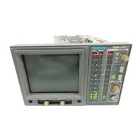
Tektronix 760A Instruction Manual (178 pages)
Stereo Audio Monitors
Brand:
Tektronix
| Category:
Speaker System
| Size: 11.14 MB
Table of Contents
Table of Contents
9
List of Figures
12
List of Tables
13
General Safety Summary
15
Service Safety Summary
17
Preface
19
Introduction and Specifications
21
Section 1 Introduction and Specifications
23
Introduction
23
Features
23
CRT Display
23
Figure 1-1: LED Bar Graph Scales for the 760A, 760D, and 760N
23
Bar Graph
24
Dynamic Response Characteristics for Peak Program Meters
24
Return Time
25
Rear Panel
25
Safety Standards
25
Table 1-1: Response Time
25
Table 1-2: Return Time
25
Specifications
26
Table 1-3: Electrical Characteristics
26
Table 1-4: Environmental Limits
28
Table 1-5: Physical Characteristics
28
Operating Instructions
29
Section 2 Operating Instructions
31
Introduction
31
Front-Panel Controls
31
Table 2-1: Front-Panel Controls
31
Rear-Panel Connectors
32
Figure 2-1: 760A Front Panel
32
CRT Display
33
Display Orientation
33
Figure 2-2: 760A Rear Panel
33
Graticule
34
Figure 2-3: 760A Sound Stage Graticule
34
Figure 2-4: 760A X-Y Graticule
34
Led Bars
35
Using the 760A / 760D / 760N
36
Initial Alignment
36
Level Setups
37
System Phase Error Measurements
37
Energy Distribution
38
Figure 2-5: Ellipse with Approximately 13° Phase Error
38
Figure 2-6: Strong Left Content
38
Monaural Compatibility
39
Polarity Reversal
39
Figure 2-7: Well Balanced Stereo
39
Figure 2-8: Stereo Unsuited to Monaural Reception
39
Clipping
40
Figure 2-9: Severe Clipping of Stereo Signal
40
Section 3 Installation
43
Electrical Installation
45
Power Source
45
Mains Frequency and Voltage Ranges
45
Changing Input Sensitivity (Standard 760A Only)
45
Table 3-1: Factory Set Input Sensitivity
45
User-Definable Input Sensitivity (Standard 760A Only)
46
Changing Input Termination
46
Changing Display Orientation
46
Figure 3-1: 760A / 760D / 760N Jumper Locations
47
Section 4 Maintenance
49
Introduction
51
Preventive Maintenance
51
Cleaning
51
Visual Inspection
52
Static-Sensitive Components
52
Performance Checks and Readjustments
52
Corrective Maintenance
52
How to Use this Manual
52
Figure 4-1: Using the Foldout Pages
53
Figure 4-2: Circuit Board Locations in the 760A/760D/760N
54
Obtaining Replacement Parts
55
Troubleshooting Information
55
DAC Servicing
55
PAL Signal Specification
56
Power Supply Troubleshooting Procedure
57
Introduction
57
Low Volts Supply
58
Table 4-1: Power Supply Fault Symptoms
58
Table 4-2: Low Volts Supply Voltages
58
High Volts Supply
60
Table 4-3: Control Circuit Test Points
60
Table 4-4: High Volts Supply Fault Symptoms
61
Table 4-5: High Voltage Oscillator Test Points
62
Mechanical Disassembly and Assembly
63
Bezel Removal
63
Figure 4-3: Bezel Removal
63
Graticule Light Removal and Replacement
64
CRT Removal
64
CRT Replacement
64
Rear Panel Removal and Replacement
65
Main Board Removal and Replacement
66
Figure 4-4: Retaining Screw Locations
66
LED Bar and Socket Removal and Replacement
66
Power Supply Board Removal and Replacement
67
Repackaging
67
Figure 4-5: Repackaging the 760A/760D/760N
68
Performance Check and Calibration
69
Section 5 Performance Check and Calibration Procedures
71
Introduction
71
Required Test Equipment
71
Performance Check Procedure
72
Table 5-1: Verifying Input Sensitivity (760A Only)
75
Calibration Procedure
81
Figure 5-2: 760-Series Adjustment Locations
82
Table 5-2: LED Bar Gain Adjustment
85
Table 5-3: LED Bar Reference Adjustment
85
Theory of Operation
87
Section 6 Theory of Operation
89
Introduction
89
Block Diagram
89
Detailed Circuit Descriptions
89
Input Amplifiers <1
89
Matrix & Agc Control Logic <4
90
Figure 6-1: 760A / 760D / 760N Block Diagram
90
Agc & Crt Deflection Amplifiers <5
91
Level Indicators
91
Graph Drivers <2
92
Dynamic Response Control (Left)
92
Signal Peak Processor (Left)
92
Figure 6-2: Simplified Level Indicator Block Diagram
92
Bar Anode Driver (Left)
93
Peak Hold On/Off
93
Bar Scanner/Driver & Dac <3
94
Master Clock
94
Down Counter
94
Scale Shaper Lookup Table
94
Line Rectifier and Filter
95
Output Filters
96
High Voltage Power Supply <7>
97
Power Supply Outputs
98
Figure 6-3: Pinout of the CRT Socket
99
Table 7-1: Power Cord Options
103
Section 7 Options
103
Section 8 Replaceable Electrical Parts
107
Column Descriptions
108
Cross Index – Mfr. Code Number to Manufacturer
109
Replaceable Electrical Parts
111
Diagrams/Circuit Board Illustrations
131
Diagrams and Circuit Board Illustrations
155
Replaceable Mechanical Parts
155
Column Descriptions
156
Advertisement
Related Products
Tektronix 760D
Tektronix 760N
Tektronix 7603
Tektronix 764
Tektronix 7623
Tektronix 7623A
Tektronix 7612D
Tektronix 7613
Tektronix 7D11
Tektronix 7B53N
Tektronix Categories
Test Equipment
Measuring Instruments
Amplifier
Portable Generator
Printer
More Tektronix Manuals
Login
Sign In
OR
Sign in with Facebook
Sign in with Google
Upload manual
Upload from disk
Upload from URL