Sign In
Upload
Manuals
Brands
Tektronix Manuals
Test Equipment
455
Tektronix 455 Analog Oscilloscope Manuals
Manuals and User Guides for Tektronix 455 Analog Oscilloscope. We have
1
Tektronix 455 Analog Oscilloscope manual available for free PDF download: Instruction Manual
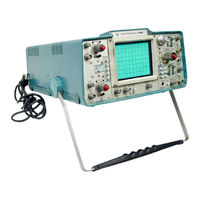
Tektronix 455 Instruction Manual (247 pages)
PORTABLE OSCILLOSCOPE
Brand:
Tektronix
| Category:
Test Equipment
| Size: 23.58 MB
Table of Contents
Instrument Serial Numbers
3
Table of Contents
4
Main M Odule
6
List of Illustrations
7
Operators Safety Summary
10
Symbols
10
Grounding the Product
11
Use the Proper Fuse
11
Use the Proper Power Cord
11
Servicing Safety Summary
12
Section 1 - Specifications
14
Physical
17
B2 Horizontal M Odule
20
455/A2/B2
24
Recommended Accessories
24
Section 2 - Operating Instructions
26
O Perating Voltage
26
Safety Inform Ation
26
Functions of Controls, Connectors and Indicators
26
Main M Odule
26
A2 Vertical M Odule
28
Ac Gnd
29
Operating Lnstructions-455/A2/B2
29
UNCA Lamps
29
VERT Mode
29
B2 Horizontal M Odule
30
Horiz Display
31
Position
31
Trig Mode
31
X10 Mag
31
Coupling
32
Power
32
Source
32
Trigger Level
32
Dual Trace Phase Difference Measurement
33
Instantaneous Amplitude Measurement
33
Peak-To-Peak Amplitude Measurements
33
Basic a Pplications and Measurements
33
High Resolution Phase Measurement
34
Common Mode Rejection
35
Cascaded Operation
35
Time Duration Frequency Measurements
35
Risetime Measurements
36
Differential Time Measurements
36
Delayed Sweep Magnification
38
Options
40
Test Equipment Required
40
Section 3 - Performance Check
40
Performance Check Procedure
41
Prelim Inary Procedure
41
Trigger View Gain
43
Trigger View Delay Difference
43
Cascaded Sensitivity
44
Cascaded Bandwidth
44
CH1 Bandwidth
44
X Bandwidth
45
Trigger Filter
45
Low Frequency Triggering
45
External Triggering
47
Internal Triggering
48
Trigger Level Ranges
48
A and B Sweep Rate Accuracy
49
Magnified Sweep Accuracy
50
Differential Time Measurement Accuracy
50
Basic Circuit Functions
53
Section 4 - Circuit Description
53
A2 Vertical M Odule
53
B2 Horizontal M Odule
54
Detailed Circuit Operation
55
Calibrator
55
Multivibrator
55
Output Amplifier
55
Sweep Gate a M Plifier
55
455/A2/B2
55
High-Voltage Oscillator
56
High-Voltage Regulator
56
C Rt C Ircu It
56
High-Voltage Circuitry
57
Crt Control Circuits
57
Z Axis Amplifier
57
Low-Voltage Power Supply
57
Power Input
57
Secondary Circuit
58
Scale Factor Control
59
Input Coupling and Volts/Division Switching
59
FET Input Source Follower
59
Preamplifier and Channel Switching Gates
59
Channel Switching Multivibrator
62
Vertical Output Amplifier
63
Delay-Line Driver
63
Normal Trigger Pickoff
63
Trigger Coupling
64
Input Source Follower
64
Trig G er Input
64
Trigger, Sweep, and H Orizontal Pream Plifier
64
A and B Trigger Generators
64
Sweep Generator IC's
67
Miller Sweep Generator
67
Sweep Control 1C
68
Sweep Control Operation
69
A Sweep Mode
69
B D Ly'D Sweep Mode
70
A Inten Sweep Mode
70
Horizontal Preamplifier 1C
71
Cabinet Removal
73
Cleaning
73
Section 5 - Maintenance
73
Preventive M Aintenance
73
Interior
73
Switch Contacts
74
Exterior
74
Visual Inspection
74
Lubrication
74
Crt
74
Sem Iconductor Checks
74
Recalibration
74
Special Parts
75
Standard Parts
75
C Orrective M Aintenance
75
O Btaining Replacement Parts
75
Ordering Parts
75
Soldering Techniques
75
Cabinet Bottom Removal
76
C Om Ponent Removal and Replacement
76
Fig. 5-1. Rear-Panel Assembly Removal
76
Interconnecting Cable and Pin C Onnector Replacement
76
Fig. 5-3. Pin Connector Replacement
77
Cathode Ray Tube (Crt) Removal
78
Shaft-Knob Removal
78
Fig. 5-5. Vertical Module Removal
79
Fig. 5-6. LED Replacement
79
Scale-Factor LED Replacement
79
Vertical M Odule Removal
79
Fig. 5-7. VO LTS/DIV Sw Itch Disassembly
80
Actuator Assembly Replacement Considerations
81
Substrate or Contact Replacement Considerations
81
VO LTS/DIV Sw Itch Assem Bly Removal
81
Fig. 5-8. Hybrid 1C Replacement
82
Hybrid 1C Removal
82
Board Locations
83
Fig. 5-10. Circuit Board Locations
83
Fig. 5-9. Horizontal Module Removal
83
H Orizontal M Odule Removal
83
A and B Timing Switch Board Removal
84
Horizontal Board Removal
85
Trigger Board Removal
85
Circuit Board Illustrations
86
Component Value Identification
86
Semiconductor Lead Configurations
86
Troubleshooting Aids
86
Troubleshooting Chart
86
Diagrams
86
Troubleshooting Equipment
86
Fig. 5-12. Component Value Identification
87
Troubleshooting Techniques
88
Check Associated Equipment
88
Check Circuit Board Interconnections
88
Check Control Settings
88
Check Individual Components
88
Check Instrument Calibration
88
Check Voltages and Waveforms
88
Isolate Trouble to a Circuit
88
Visual Check
88
Repair and Readjust the Circuit
89
Fig. 5-13. Troubleshooting Chart
90
Repackaging for Shipment
92
Tolerances
93
Partial Procedures
93
Section 6 - Adjustments
93
Adjustm Ent Interaction
93
Test Equipment Required
93
A. M a in Module
95
Prelim Inary Procedure
95
Procedure
95
Fig. 6-2. Z Axis Com Pensation Adjustm Ent Location
96
Fig. 6-3. Crt and Calibrator Adjustment Locations
97
Vertical M Odule
98
Fig. 64. Vertical Adjustment Locations
101
C. Ho R Izo N Ta L Module
102
Fig. 6 5. Sweep Adjustment Locations
102
Fig. 6-6A Horizontal and T Rigger Adjustm Ent Locations
103
Fig. 6-6B. Horizontal and Trigger Adjustment Locations
103
Fig. 6-7. C232 and C233 Adjustment Locations
105
Instrument Options
106
Fig. Option 4-1. Partial Power Supply Diagram
107
Installation and Set up of Video Gratitude
110
Operating Information
110
Triggering a Sweep
110
Dual Trace Modes
111
One Frame a Sweep Cycle
111
Selecting an Individual Line
111
Vertical Operating Modes
111
CCIR System B
112
Identifying Fields, Frames and Lines
112
Fig. Option 5-1. Block Diagram
116
Switching
116
Input Buffer Amplifier
117
Inverting/Non Inverting Amplifier
117
Sync Separator Circuit
117
Vertical Sync Recognizer
118
Voltage Conditions
119
Waveform Conditions
119
Abbreviations
122
Replaceable Parts
122
Functions of Controls and Connectors
125
Safety Considerations
125
Detailed Circuit Description
127
DC Input
128
Inverter Circuit
128
Turn off Circuit
128
Inverter Balance
130
Operating Range
130
Replaceable Electrical Parts
139
Diagrams and Circuit Board Illustrations
163
Main M Odule
166
A2 Vertical M Odule
168
Advertisement
Advertisement
Related Products
Tektronix 454A
Tektronix 453
Tektronix 453A
Tektronix 442
Tektronix 465M
Tektronix 465
Tektronix 464
Tektronix 465B
Tektronix 475
Tektronix 468
Tektronix Categories
Test Equipment
Measuring Instruments
Amplifier
Portable Generator
Printer
More Tektronix Manuals
Login
Sign In
OR
Sign in with Facebook
Sign in with Google
Upload manual
Upload from disk
Upload from URL