Sign In
Upload
Manuals
Brands
TECO Manuals
Relays
SG2-20HR-12D
User Manuals: TECO SG2-20HR-12D Logic Relay
Manuals and User Guides for TECO SG2-20HR-12D Logic Relay. We have
3
TECO SG2-20HR-12D Logic Relay manuals available for free PDF download: User Manual, Equipment Operation Manual
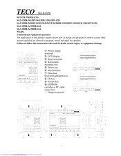
TECO SG2-20HR-12D User Manual (270 pages)
SG2 series Programmable Logic Smart Relay Smart PLC
Brand:
TECO
| Category:
Relays
| Size: 7.03 MB
Table of Contents
Table of Contents
2
Summary of Changes
6
Chapter 1: Getting Started
9
Examination before Installation
10
Environmental Precautions
10
SG2 Model Identification
10
Examination before Installation
11
Environmental Precautions
11
SG2 Model Identification
11
Quick Start Setup
11
Quick Start Setup
12
Install SG2 Client Software
12
Connect Power to SG2 Smart Relay
12
Establish Communication
12
Connect Programming Cable
13
Establish Communication
13
Write Simple Program
13
Write Simple Program
14
Chapter 2: Installation
18
General Specifications
18
General Specifications
19
Product Specifications
22
Mounting
23
Wiring
25
K Type Indicator Light
27
Chapter 3 Program Tools
28
PC Programming Software "SG2 Client
29
Chapter 3 Program Tools
29
Connecting the Software
29
Installing the Software
29
Start Screen
29
Ladder Logic Programming Environment
30
Menus, Icons and Status Bar
31
Programming
32
Establish Communication
33
Simulation Mode
33
Writing Program to Smart Relay
34
Online Monitoring/Editing
35
Operation Menu
36
Hmi/Text
37
Program Documentation
41
Analog Output Set
43
3-Row/5-Row
44
Data Register Set
45
View Menu
47
FBD Programming Environment
48
Menu, Icons and Status Bar
48
Programming
49
Online Monitoring/Editing
50
Simulation Mode
50
Symbol and Parameters List
51
Keypad
54
Original Screen
55
LCD Display Main Menu
58
Memory Cartridge (Sold Separately)
53
LCD Display and Keypad
54
RTC Daylight Saving Setting
63
SG2 System Error
67
Chapter 4: Parameter Passing
68
SG2 Inner Data Type
69
Passing Parameter out of Range
71
Chapter 5: Relay Ladder Logic Programming
73
Common Memory Types
74
Basic Elements
74
Specialty Memory Types
77
Specialty Elements
77
Output Instructions
78
Analog Memory Type
79
Analog Elements
79
Timer Instruction
80
Counter Instructions
88
Real Time Clock (RTC) Instructions
98
Comparator Instructions
106
HMI Display Instructions
108
PWM Output Instruction (DC Transistor Output Models Only)
111
IO Link/Remote I/O Instruction (SG2-20Vxxx Model Only)
114
MU (Modbus) (SG2-20Vxxx Model Only)
117
SHIFT (Shift Output)
124
AQ (Analog Output)
125
AS (Add-Subtract)
127
MD (Mul-DIV)
128
PID (Proportion- Integral- Differential)
129
MX (Multiplexer)
133
AR (Analog-Ramp)
134
DR (Data Register)
138
Chapter 6: Function Block Diagram Programming
140
FBD Instructions
141
FBD System Memory Space
142
Analog
144
Analog Input
144
Analog Output
145
Coil Block Instruction
146
Hmi
147
PWM Function Block (Only Transistor Output Version)
148
IO Link Function Block
150
SHIFT Function Block
152
Logic Block Instructions
153
AND Logic Diagram
153
AND (EDGE) Logic Diagram
153
NAND Logic Diagram
154
NAND (EDGE) Logic Diagram
154
OR Logic Diagram
154
NOR Logic Diagram
155
XOR Logic Diagram
155
SR Logic Diagram
155
NOT Logic Diagram
155
Pulse Logic Diagram
156
BOOLEAN Logic Diagram
156
Function Block
157
Timer Function Block
158
Common Counter Function Block
166
High Speed Counter Function Block (DC Version Only)
172
RTC Comparator Function Block
174
Analog Comparator Function Block
179
AS (ADD-SUB) Function Block
182
MD (MUL-DIV) Function Block
183
PID (Proportion- Integral- Differential) Function Block
184
MX (Multiplexer) Function Block
185
AR (Analog-Ramp) Function Block
186
Example
189
DR (Data-Register) Function Block
190
MU (Modbus) Function Block
191
Chapter 7 Hardware Specification
197
Normal Specification
198
Product Specifications
199
Power Specifications
200
Normal Model Machine Specifications
200
12V DC Model Specifications
201
24V AC Model Specifications
201
Power Circuitry Diagram
202
Input Specifications
203
100~240V AC Model
203
24V DC, 12 I/O Model
204
24V DC, 20 I/O Model
205
12V DC, 12 I/O Model
206
12V DC, 20 I/O Model
207
Output Specifications
208
Output Port Wiring Notice
208
Light Load
208
Inductance Load
209
Life of Relay
209
Size Diagram of SG2
210
Chapter 8: 20 Points RS485 Type Models Instruction
211
Communication Function
212
Detail Instruction
214
Remote IO Function
214
IO Link Function
215
MU Instruction (Modbus RTU Master)
217
Modbus RTU Slave Function
219
SG2 Modbus Protocol
219
Chapter 9 Expansion Module
222
Summarize
222
Power
224
Size
224
Digital IO Module
227
Analog Module
231
Analog Input Module 4AI
231
Temperature Input Module 4PT
232
Analog Output Module 2AO
233
Communication Module
235
MBUS Module
235
DNET Module
238
PBUS Module
241
EN01 (TCP/IP) Module
244
Appendix: Keypad Programming
250
Appendix A: Keypad Programming in Ladder Mode
251
Appendix B: Keypad Programming in Ladder FUNCTION BLOCK
255
Advertisement
TECO SG2-20HR-12D User Manual (26 pages)
Smart PLC
Brand:
TECO
| Category:
Relays
| Size: 1.34 MB
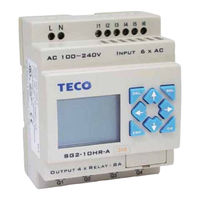
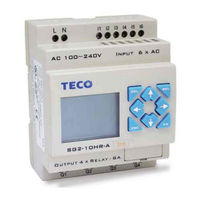
TECO SG2-20HR-12D Equipment Operation Manual (4 pages)
SG2 H series
Brand:
TECO
| Category:
Controller
| Size: 0.46 MB
Advertisement
Advertisement
Related Products
TECO SG2-20HR-D
TECO SG2-20HR-A
TECO SG2-20HR-24A
TECO SG2-20HT-D
TECO SG2-20VR-D
TECO SG2-20VT-D
TECO SG2-20KR-D
TECO SG2-20KR-A
TECO SG2-20CT-D
TECO SG2-20CR-D
TECO Categories
Inverter
Air Conditioner
Refrigerator
Chiller
Controller
More TECO Manuals
Login
Sign In
OR
Sign in with Facebook
Sign in with Google
Upload manual
Upload from disk
Upload from URL