Sign In
Upload
Manuals
Brands
Taylor-Dunn Manuals
Utility Vehicle
B 2-48
Taylor-Dunn B 2-48 Manuals
Manuals and User Guides for Taylor-Dunn B 2-48. We have
2
Taylor-Dunn B 2-48 manuals available for free PDF download: Operation, T Roubleshooting And Replacement Parts Manual
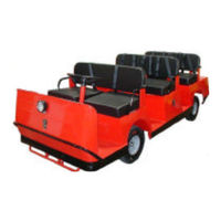
Taylor-Dunn B 2-48 Operation, T Roubleshooting And Replacement Parts Manual (292 pages)
EQUIPPED WITH GT-DRIVE SYSTEM
Brand:
Taylor-Dunn
| Category:
Utility Vehicle
| Size: 29.47 MB
Table of Contents
Taylor-Dunn
5
Table of Contents
5
About this Manual
8
Introduction
8
Responsibilities
9
Who Should Read this Manual
9
How to Use this Manual
10
Safety Rules and Operating Instructions
10
Conventions
11
How to Identify Your Vehicle
12
Taking Delivery of Your Vehicle
14
Table of Contents
15
Standard Specifications* (Common)
16
Standard Specifications* (Model B 2-48/2-54)
17
Standard Specifications* (Model BT 2-48)
18
Standard Specifications* (Model BT 2-80)
19
Driver Training Program
20
Driver Qualifications
20
Safety Rules and Guidelines
20
Dash up to Serial # 179669
21
Accessory Switch (Optional)
21
Headlight Switch
21
Hi-Low Switch (Optional)
21
Smart View Display
21
Forward-Off-Reverse Switch
21
Horn Switch
21
Key-Switch
21
Vehicle Controls
21
Dash Starting Serial #179670
22
Headlight Switch
22
Wiper Switch (Optional)
22
Strobe Switch (Optional)
22
Forward-Off-Reverse Switch
22
Hi-Low Switch (Optional)
22
Smart View Display
22
Horn Switch
22
Key-Switch
22
Directional Signals (Optional)
23
Steering
23
Hazard Light Switch (Optional)
23
Accelerator Pedal
23
Foot Brake Pedal
23
Charger Interlock
24
Seat Interlock Switch
24
Electrolyte Alarm (Optional)
24
Park Brake
24
Trailer Brake Module (Optional)
25
Smart View Display
26
Fault Code Tables
28
Vehicle Operation Guidelines
29
Safety Guidelines
29
Starting
29
While Driving
29
Loading and Unloading
29
Towing Loads
29
Parking
30
Automatic Electric Park Brake
30
Towing this Vehicle
30
Dump Bed (Optional)
31
Operation
31
Service
31
Lowering the Dump Manually
32
Lubrication
32
Hydraulic Pump Exploded View
33
Charging Your Vehicle
34
Signet Charger Operation, Model HB Series
34
Signet Charger Operation, Model HBS Series
34
New Battery Break in
35
Charging Time
35
Storing / Returning to Service
35
Storing Your Vehicle
35
Returning to Service
35
Periodic Maintenance Checklist
36
Standard Periodic Maintenance Schedule for the Smart View Display
37
Daily Visual Inspection
38
Maintenance Guidelines for Severe Duty Applications
38
General Maintenance
39
Troubleshooting Guide
41
Lubrication Chart
42
Front Axle Service
43
Inspect the Front Wheel Bearings and King Pin
44
Adjust Front Wheel Bearings
45
Front Axle Removal and Installation
46
Removal
46
Installation
47
Steering Component Service
47
Front Axle Disassembly
48
Replace Front Wheel Bearings
49
Replace the King Pins and Bushings
51
Replace the Steering Knuckle
53
Steering Component Service
55
Front End Alignment
56
Inspect Ball Joints
60
Inspect Rod Ends
61
Adjust the Steering Gear
62
Replace the Steering Shaft
64
Replace the Steering Wheel
66
Replace the Steering Gear
67
Replace the Ball Joints, Tie Rods, and Drag Link
68
Replacing the Drag Link
70
Replacing the Tie Rod
71
Center the Steering Gear
72
Pitman Shaft Alignment
72
Repair the Steering Gear
73
Exploded View of Steering Gear
76
Brake Service
77
Brakes Service
77
Inspect the Service Brake
78
Disc Brake Pads
78
Disc Brake Rotor
79
Inspect the Parking Brake
80
Wheel Park Brake (Hydraulic Disc)
80
Electric Motor Brake
81
Adjust the Service Brakes
82
Two or Four Wheel Hydraulic Disc Brakes
82
Adjust the Parking Brake
83
Wheel Park Brake (Hydraulic Disc)
83
Check Master Cylinder Fluid
84
Bleed the Brake System
85
Flush the Brake System
87
Replace the Parking Brake Lining (Electric Motor Brake)
88
Inspection
90
Replace Front Disc Brake Pads
91
Replace Rear Brake Pads
93
Hydraulic Disc
93
Replace the Wheel Cylinder
95
Disc Brake Body Assembly (Front or Rear)
95
Repair the Brake Body
97
Replace the Master Cylinder
99
Repair the Master Cylinder
101
Motor Service
103
Inspecting the Motor Brushes
104
Motors with Internal Cooling Fans
104
Motor Inspection
105
Motor Removal and Installation
105
Replacing the Brushes or Armature Bearing
109
Repairing the Commutator
110
Service Limits
112
Transmission
113
Check Oil Level
114
Change Oil
115
Motor Removal and Installation
116
Rear Hub or Rotor
117
Tires and Wheels
117
Removing and Installing the Rear Axles (Disc Brakes)
118
Transmission Assembly
120
Remove and Install
120
Disassembly and Reassembly of the Primary Reduction Gear Case
121
Disassembling the 3Rd Member
124
Assembling the 3Rd Member
127
Pinion Bearing Preload
130
Pinion Gear Shimming Instructions
131
Setting the Pinion Gear Depth
131
Suspension
133
Replace the Rear Springs
134
Replace the Front Springs
135
Replace the Spring Bushings
136
Replace the Shocks
137
Tires and Wheels
139
Tire Inflation
140
Tire Inspection
140
Replace the Tire/Wheel
141
Repair the Tire (Pneumatic)
142
Replace the Tire (Pneumatic)
143
Battery Service
145
Cleaning
146
Testing
147
Watering
149
Charging
150
Replacing (6-Volt Batteries Only)
151
Moist Charge Batteries
153
Storage and Returning to Service
154
Storage
154
Returning to Service
155
Sevcon Control System Troubleshooting
157
Control System Troubleshooting
157
Definitions
158
Important Notes and Instructions
158
Terminology Used
158
Test Equipment Required
158
Identifying Your Controller
159
Start Troubleshooting here
160
Test 8. Anti-Rolloff Fault
171
Test 9. Electric Motor Brake
172
Logic Voltage Reference Table
174
Status LED Code Table
175
Smart View Fault Codes
176
Turn the Key Switch off before Disconnecting the Batteries
179
Charger Troubleshooting
180
Electrical Troubleshooting
192
Clamp on DC Ammeter to Measure up to 20-Amps
196
Damage to the Charger
196
If the Charger Exhibits Intermittent Problems, It Must be in the Failed Mode for Troubleshooting
196
Make Sure that the AC Electrical Socket the Charger Is Plugged into Is in Good
196
Make Sure that the AC Voltage at the Electrical Socket Is the same as the AC
196
Make Sure the Batteries Are in Good Condition
196
There Are no Internally Serviceable Components in the Charger. if the Charger Has Failed then It Must be
196
This Troubleshooting Guide Assumes a Familiarity with the Use of a Digital Multimeter
196
Wire Diagrams
201
Wire Diagram
201
Complete Vehicle
202
Dash
203
Control Panel
204
Accelerator Module Detail
205
Lighting
206
Trailer Brake Module and Receptacle
207
Illustrated Parts
209
Front Axle
211
Steering Knuckle
213
Front Brakes
214
Front Brake
215
Steering Linkage
217
Steering Column
218
Steering Gear
221
Front Suspension
222
Transmission Gear Case
224
Rear Axle
226
Transmission Differential Case
226
Rear Brakes
229
Brake Linkage
231
Rear Suspension
232
Motor
234
Electric Brake and Rear Motor Mount
236
Master Cylinder
238
Brake Lines
240
Brake Lines with Dual Master Cylinder
240
With Single Master Cylinder
242
Wheels and Tires
244
Instrument Panel Starting S/N 179670
246
Instrument Panel up to S/N 179669
246
Resetting the Smart View Display
246
Speed Control Panel
248
Miscellaneous Electrical
250
Lighting
252
Lestronic® Charger
254
Signet® Charger
258
Batteries
260
Seat Cushions and Deck, B 2-48 and
262
Seat Cushions BT 2-48
264
Seat Cushions BT 2-80
264
Decals
266
Cab Options
268
Door Options, Steel Cab
270
Door Options, Fiberglass Cab
272
Hydraulic Dump Body Option
274
Rear Cargo Box
276
Hitches
278
Hardware Identification
284
Hex Bolts
284
Other Bolts
284
Standard Head Markings
284
Hex Lock Nuts (Stover)
285
Hex Nuts
285
Other Nuts
285
Suggested Torque Values
286
(Non-Critical Hardware)
286
Suggested Torque Values
287
(Critical Hardware)
287
Appendix A
289
Appendix B
289
Appendix C
289
Brake Lining Handling Precautions
289
Advertisement
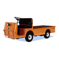
Taylor-Dunn B 2-48 Operation, T Roubleshooting And Replacement Parts Manual (232 pages)
EQUIPPED WITH AC MOTOR PEED CONTROL
Brand:
Taylor-Dunn
| Category:
Utility Vehicle
| Size: 20.05 MB
Table of Contents
Taylor-Dunn
5
Table of Contents
5
About this Manual
8
Introduction
8
Who Should Read this Manual
9
Responsibilities
9
How to Use this Manual
10
Safety Rules and Operating Instructions
10
Conventions
11
How to Identify Your Vehicle
12
Taking Delivery of Your Vehicle
13
Safety Rules and Operating Instructions
15
Standard Specifications
16
Safety Rules and Guidelines
17
Driver Training Program
18
Driver Qualifications
18
Dash up to Serial #179501
19
Horn Switch
19
Forward-Off-Reverse Switch
19
3A) Light Switch
19
3B) Hi-Low Switch
19
Combination Display
19
Accessory Switches (Optional)
19
Vehicle Controls
19
Key-Switch
19
Emergency Stop Switch
19
Strobe Switch (Optional)
20
Forward-Off-Reverse Switch
20
Hi-Low Switch (Optional)
20
Smart View Display
20
Horn Switch
20
Key-Switch
20
Wiper Switch (Optional)
20
Headlight Switch
20
Dash Starting Serial #1795002
20
Combination Display
21
Charger Interlock
23
Vehicle Operational Guidelines
24
Safety Guidelines
24
Starting
24
While Driving
24
Loading and Unloading
25
Parking
25
Towing
25
Adjustable Controller Parameters
26
Charging Your Vehicle
28
New Battery Break in
28
Charging Time
28
Industrial Charger Operation
28
Signet Charger Operation, Model HB Series
29
Signet Charger Operation, Model HBS Series
29
Storing and Returning to Service
30
Storing Your Vehicle
30
Returning to Service
30
Periodic Maintenance Checklist
31
Daily Visual Inspection
32
Maintenance Guidelines for Severe Duty Applications
32
General Maintenance
33
Troubleshooting Guide
35
Lubrication Chart
36
Front Axle Service
37
Inspect the Front Wheel Bearings and King Pin
38
Adjust Front Wheel Bearings
39
Front Axle Removal and Installation
40
Removal
40
Installation
41
Steering Component Service
41
Front Axle Disassembly
42
Replace Front Wheel Bearings
43
Replace the King Pins and Bushings
45
Replace the Steering Knuckle
47
Steering Component Service
49
Front End Alignment
50
Inspect Ball Joints
54
Inspect Rod Ends
55
Adjust the Steering Gear
56
Replace the Steering Shaft
58
Replace the Steering Wheel
60
Replace the Steering Gear
61
Replace the Ball Joints, Tie Rods, and Drag Link
62
Replacing the Drag Link
64
Replacing the Tie Rod
65
Center the Steering Gear
66
Pitman Shaft Alignment
66
Repair the Steering Gear
67
Exploded View of Steering Gear
70
Brake Service
71
Brakes Service
71
Inspect the Service Brake
72
Disc Brake Pads
72
Disc Brake Rotor
73
Inspect the Automatic Parking Brake
74
Adjust the Automatic Parking Brake
74
Adjust the Service Brakes
74
Check Master Cylinder Fluid
75
Bleed the Brake System
76
Flush the Brake System
78
Replace Front Disc Brake Pads
79
Replace Rear Brake Pads
81
Hydraulic Disc
81
Replace the Wheel Cylinder
83
Disc Brake Body Assembly (Front or Rear)
83
Replace the Master Cylinder
85
Repair the Master Cylinder
87
Transmission
89
Check Oil Level
90
Change Oil
91
Motor Removal and Installation
92
Rear Hub or Rotor
93
Removing and Installing the Rear Axles (Disc Brakes)
94
Transmission Assembly
96
Remove and Install
96
Disassembly and Reassembly of the Primary Reduction Gear Case
97
Disassembling the 3Rd Member
100
Assembling the 3Rd Member
103
Pinion Bearing Preload
106
Pinion Gear Shimming Instructions
107
Setting the Pinion Gear Depth
107
Suspension
109
Replace the Rear Springs
110
Replace the Front Springs
111
Replace the Spring Bushings
112
Replace the Shocks
113
Tires and Wheels
113
Tires and Wheels
115
Tire Inflation
116
Tire Inspection
116
Replace the Tire/Wheel
117
Repair the Tire (Pneumatic)
118
Replace the Tire (Pneumatic)
119
Battery Service
121
Cleaning
122
Testing
123
Watering
125
Charging
126
Replacing (6-Volt Batteries Only)
127
Moist Charge Batteries
129
Storage and Returning to Service
130
Storage
130
Returning to Service
131
Control System Diagnostics
135
Important Notes and Instructions
136
Test Equipment Required
136
Status LED Code Table
137
Throttle Module Test
140
Wire Diagram
142
Electrical Troubleshooting
154
Clamp on DC Ammeter to Measure up to 20-Amps
158
Damage to the Charger
158
If the Charger Exhibits Intermittent Problems, It Must be in the Failed Mode for Troubleshooting
158
Make Sure that the AC Electrical Socket the Charger Is Plugged into Is in Good
158
Make Sure that the AC Voltage at the Electrical Socket Is the same as the AC
158
Make Sure the Batteries Are in Good Condition
158
There Are no Internally Serviceable Components in the Charger. if the Charger Has Failed then It Must be
158
This Troubleshooting Guide Assumes a Familiarity with the Use of a Digital Multimeter
158
Illustrated Parts
163
Front Axle
164
Steering Knuckle
166
Steering Linkage
168
Steering Column
170
Front Suspension
172
Steering Gear
172
Rear Suspension
174
Transmission Gear Case
176
Rear Axle
178
Transmission Differential Case
178
Rear Brakes
180
Front Brake
181
Brake Lines
182
Master Cylinder
182
Motor
184
Motor Mount
186
Wheels and Tires
188
Instrument Panel Starting Serial # 179502
190
Instrument Panel up to Serial # 179501
190
Speed Control Panel
192
Wire Harnesses
192
Resetting the Maintenance Meter Function
193
Miscellaneous Electrical
194
Lighting
196
Lestronic® Charger
198
Signet® Charger
202
Portable Charger Wiring
203
Batteries
204
Seat Cushions and Deck
206
Mirrors
208
Miscellaneous Frame Components
208
Decals
210
Cab Options
212
Door Options, Steel Cab
214
Door Options, Fiberglass Cab
216
Hydraulic Dump Body Option
218
Rear Cargo Box
220
Top Covers
220
Hitches
222
Ladder Rack Option B2-004-66 and B2-006-78
223
Appendix B
225
Brake Lining Handling Precautions
225
Appendix A: Special Tools
226
Hex Bolts
227
Other Bolts
227
Hardware Identification
227
Hex Nuts
228
Hex Lock Nuts (Stover)
228
Other Nuts
228
Suggested Torque Values (Non-Critical Hardware)
229
Appendix C: Brake Lining Handling Precautions
231
Advertisement
Related Products
Taylor-Dunn B 2-54
Taylor-Dunn B 2-10
Taylor-Dunn BurdenMaster B 2-00
Taylor-Dunn B0-254-48
Taylor-Dunn B0-015-00
Taylor-Dunn B0-254-36
Taylor-Dunn BF-030-48
Taylor-Dunn B0-T48-72AC
Taylor-Dunn B 1-05
Taylor-Dunn B0-248-48
Taylor-Dunn Categories
Utility Vehicle
Electric Vehicles
Trucks
Tractor
Automobile
More Taylor-Dunn Manuals
Login
Sign In
OR
Sign in with Facebook
Sign in with Google
Upload manual
Upload from disk
Upload from URL