Sign In
Upload
Manuals
Brands
Takeuchi Manuals
Compact Excavator
TB216
Takeuchi TB216 Manuals
Manuals and User Guides for Takeuchi TB216. We have
2
Takeuchi TB216 manuals available for free PDF download: Workshop Manual, Operator's Manual
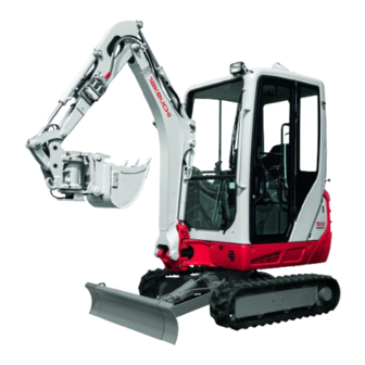
Takeuchi TB216 Workshop Manual (304 pages)
Brand:
Takeuchi
| Category:
Excavators
| Size: 35.37 MB
Table of Contents
Directional Terms: Front, Rear, Left, Right
2
Manual Structure
2
Machine Serial Number
2
Symbols Used in this Manual
2
Safety
3
Safety Alert Symbol
4
Safety Label
4
Safety Precautions
5
Explosionproof Lighting
6
When the Canopy Is Tilted up
6
Prepare the Work Area
6
Stop the Engine before Performing Maintenance
6
Handling of the Accumulator
9
Disconnect the Battery
9
Disposing of Wastes
10
Checks after Maintenance
10
Cautions When Working
11
When Disassembling or Assembling
11
When Removing/Installing the Hydraulic Unit
11
Pressure Adjustment for Hydraulic Devices
12
Handling of Seals
12
Service Data
13
Dimensional Drawing
14
Machine Dimensions
14
Operating Range
16
Specification Tables
18
Lubricant and Fuel Chart
27
Diesel Fuel Standards
28
Performance Criteria
29
Standard Values Table
29
Hydraulic Pump Assignment Table
31
Methods for Inspecting Performance
32
Hydraulic Oil Pressure (Boom, Arm, Dozer Blade)
32
Measurement Method
32
Hydraulic Oil Pressure (Slew)
33
Hydraulic Oil Pressure (Pilot Pressure)
33
Traveling Attitude
34
Travel Speed (5 Revs.)
34
Straight-Ahead Traveling
34
Travel Speed (10 M)
34
Natural Travel Drop
35
Slew Time
35
Overrun When Slewing Stops
35
Natural Slew Drop
35
Boom Cylinder Speed
36
Arm Cylinder Speed
36
Bucket Cylinder Speed
36
Dozer Blade Cylinder Speed
36
Swing Cylinder Speed
37
Natural Cylinder Drop
37
Swing
37
Spanner Cylinder Speed
37
Slew Bearing Play
38
Backlash
38
Lever Play
38
Lever Operating Force
38
Track Tension
39
Tightening Torque
40
Hydraulic Hose
40
Bite-Type Pipe Fitting for Steel Pipe
40
Joint for Piping
41
Joint for Piping (O-Ring Seal Type)
41
Bolts and Nuts (JIS Strength Category 10.9)
42
Hydraulic Circuit Diagram
45
Control Valve
46
Main Pump
46
Slew Motor
46
Travel Motor
47
Solenoid Valve (Lever Lock and Travel Speed Switching)
47
Boom Cylinder
47
Wiring/Cable Colors
50
Wire/Cable Color Symbols
50
Types of Wire to Use
50
Electrical Circuit Diagram
50
Electrical Schematic Diagram
51
Wire Harness Diagram
52
Wiring Diagram
52
Body Harness: 03342-68000
53
Hydraulic Pump (Piston)
59
Discharge Volume Control Mechanism
59
Gear Pump
61
When the Spools Are in the Neutral Position
62
Load Check Valve
62
When the Spool Is Being Operated
62
Main Relief Valves
63
The Relief Valve Is Activated
63
Port Relief Valve
64
The Relief Valve Is Subjected to the Relief Operation
64
Anti-Cavitation Valve
66
Anti-Drift Valve
66
When the Switch Valve Is Not Activated
67
Switch Valve
67
When the Switch Valve Is Activated
67
Arm in Regeneration
68
Pilot Valve (Control Lever)
69
Proportional Control Solenoid Valve
71
Solenoid Valve(3Rd Auxiliary Line Piping)
72
Solenoid Valve
72
When the Solenoid Is Energized
72
Solenoid Valve (Lever Lock)
73
Solenoid Switching and Relief Function
73
When the Solenoid Is Not Energized
73
Check Function
74
Selector Valve
75
Switching from Position a (ISO) to Position G (JCB)
77
Cylinders
79
Cushion Mechanism
79
Counterbalance Valve
80
Hydraulic Motor
80
2-Speed Mechanism
81
2-Speed Control Valve
81
Swash Plate
82
Automatic 2-Speed Switching
82
Parking Brake
83
Reduction Gears
83
Hydraulic Motor 1
84
Hydraulic Motor 2
85
Brake Valve
86
Swivel Joint
87
Selector
87
Disassembly and Assembly
88
Service Standards
89
Track Roller
89
Shoe Slider
89
Sprocket
89
Clearance for Pin and Bushing
90
Drive System
92
Engine
92
Removing the Engine
95
Installing the Engine
95
Removing the Hydraulic Pump
97
Installing the Hydraulic Pump
97
Cautions on Starting the Hydraulic Pump
97
Fuel Tank
98
Installing the Fuel Tank
99
Removing the Fuel Tank
99
Battery
100
Removing the Battery
101
Installing the Battery
101
Throttle Lever
102
Adjusting the Throttle Lever
103
Engine Speed
103
Control Force
103
Installing the Crawler
104
Travel System
104
Removing the Crawler
104
Removing the Track Roller
105
Installing the Track Roller
105
Removing the Idler and Track Adjuster
105
Installing the Idler and Track Adjuster
105
Removing the Travel Motor
106
Installing the Travel Motor
106
Slew Equipment
107
Removing the Slew Motor
108
Installing the Slew Motor
108
Removing the Slew Bearing
110
Installing the Slew Bearing
110
Upper Frame
113
Removing the Upper Frame
115
Installing the Upper Frame
115
Covers
116
Removing the Covers
117
Installing the Covers
117
Removing the Canopy
119
Operating Device
120
Control Levers
120
Attachments
127
Hoe Attachment
127
Removing the Hoe Attachment
131
Removing the Bucket
131
Installing the Bucket
131
Removing the Link
132
Installing the Link
132
Removing the Arm
132
Installing the Arm
132
Removing the Boom
133
Installing the Boom
133
Installing the Blade
134
Removing the Blade
134
Installing the Boom Bracket
134
Removing the Boom Bracket
134
Hydraulic Tank
135
Removing the Hydraulic Tank
136
Installing the Hydraulic Tank
136
Inspecting and Refilling the Oil in the Hydraulic Tank
137
Refilling the Oil
137
Tank Pressure
137
Bleeding off the Air
138
Hydraulic Pump
139
General Precautions
140
Inspection and Adjustments
146
Checking the Parts
146
Boom Section
151
Arm Section
152
Bucket Section
152
Dozer Blade Section
152
Auxiliary Section
153
Valve Assembly
155
Manually Operated Section
156
Pilot Operated Section
157
Main Relief Valve
158
Pilot Valve
160
Solenoid Valve (3Rd Auxiliary Line Piping)
169
Inspection after Disassembly
195
Piston Rod
195
Measuring the Bend
195
Tube
195
No Load Operation Test
196
Leak Test
196
External Leak
196
Bleeding Air from the Hydraulic Cylinder
196
Counter Balance Valve and Hydraulic Motor
200
General Cautions
227
Thrust Ring
230
Flange
230
Use Limit for Parts
230
About the Troubleshooting Section
233
Notes on Troubleshooting and Servicing
233
Overall Machine
234
All Systems Working, but Insufficient Force
235
Boom, Bucket, Slew and Arm Fail to Move or Are too Slow
237
Check the Pilot Relief Valve
238
Check the Limit Switch
238
Check the Lever Lock Solenoid Valve
238
Check the Fuse
238
Traveling
239
Check the Linkage
239
The Travel Lever Lock Cylinder Is Faulty
239
Right or Left Travel Is Impossible
240
Check the Spool Operation
240
Check the Counter Balance Valve
243
Check the Swivel Joint
243
Test by Switching the Main Relief Valves
243
Is the Veering Within Specs?
243
2Nd Speed Travel Is Not Possible
244
Check the Gear Pump
244
Check the 2Nd Speed Solenoid Valve
245
2Nd Speed Control Valve Is Faulty
245
Slewing
246
No Slewing Is Possible
246
Check the Slew Motor
247
Check the Slew Pressure
247
Check the Pilot Valve
247
Slew Right or Left Is Not Possible
248
Slewing Is Slow or Lacks Force
249
When Stopped on Slope, the Upperstructure Cannot Maintain Its Posture
252
Boom
253
The Boom Cylinder Does Not Move
253
Boom Cylinder Operation Is Slow or Lacks Force
255
Spontaneous Drop of the Boom Cylinder Is too Large
259
Arm
260
Arm Cylinder Does Not Move
260
Arm Cylinder Operation Is Slow or Lacks Force
262
Spontaneous Drop of the Arm Is too Large
264
Bucket Cylinder Does Not Move or Lacks Force
265
Test by Replacing the Port Relief Valve
266
Check the Bucket Cylinder
266
Spontaneous Drop of the Bucket Is too Large
267
Swing Cylinder Does Not Move
268
Boom Swing
268
Dozer Blade
270
Dozer Blade Cylinder Does Not Move or Lacks Force
270
Prescribed Pressure Is Not Supplied to the Auxiliary Lines
274
Spanner Cylinder Does Not Move or Lacks Force
275
Piston Pump
277
Monochrome LCD Cluster
288
Panel Display and LCD Specifications
288
Table of Contents
289
Normal Panel Display/Lcd Screen
290
Panel Display: Water Temperature Gauge
291
Panel Display: Fuel Gauge
292
Overheating Warning Light
293
Engine Oil Pressure Warning Light
293
Charge Warning Light
293
Panel Display: Function/Warning Lamps
293
1 Hour Meter
294
Normal Screen
294
Main Menu Screen
295
Data Selection Screen
296
Data Screen (TRIP METER)
297
Data Screen (Water Temp.)
298
Settings Selection Screen
299
Setting Screen (Clock)
300
Setting Screen (Alarm)-1
301
Setting Screen (ALARM)-2
302
Setting Screen (CONTRAST ADJ.)
303
Advertisement
Takeuchi TB216 Operator's Manual (235 pages)
Mini Excavator
Brand:
Takeuchi
| Category:
Compact Excavator
| Size: 20.97 MB
Table of Contents
Introduction
4
Serial Numbers
4
Machine Description
5
Table of Contents
7
Safety
11
General Precautions
12
Precautions When Preparing
18
Precautions When Starting
22
Precautions When Operating
24
Precautions When Stopping
33
Precautions When Transporting
34
Precautions on Maintenance
36
Safety Signs (Decals)
45
Controls
51
Names of Components (Cab)
52
Names of Components (Canopy)
54
Covers
56
Starter Key
56
Maintenance Cover
56
Fuse Box
57
Tool Case
57
Grease Gun Holder
57
Fuel Lid
58
Fuel Filler Port
58
Side Cover
59
Engine Hood
59
Cab
60
Cab Door
60
Emergency Exit
60
Front Window
61
Lower Front Window
62
Side Window
62
Emergency Hammer (Optional)
63
Seat and Seat Belt
64
Seat (if Equipped)
64
High-Back Seat (if Equipped)
65
Seat Belt
66
Instrument Cluster
68
Warning Lamps
68
Indicators
69
Meters
69
Multi-Data Display
70
Switches
76
Starter Switch
76
Horn Button
76
Travel Speed Switch
76
Wiper Switch
77
Second Auxiliary Hydraulic Switch
77
Third Auxiliary Hydraulic Switch and Button
77
Overload Warning Switch (if Equipped)
78
Levers and Pedals
79
Safety Lock Lever
79
Throttle Lever
79
Operating Levers
80
Blade Lever
80
Travel Levers/Pedals
81
Boom Swing Pedal
81
Auxiliary Hydraulic Pedal
82
Selector Lever
82
Accessories
84
Heater
84
Cup Holder
86
Interior Light
86
Inside Rear View Mirror (Cab)
86
Power Sockets
87
Armrest
87
Radio (for Cab)
88
Auxiliary Hydraulic Lines
92
Accumulator (if Equipped)
96
Operation
97
Before Starting Operation
98
Getting on or off the Machine
98
Walk-Around Inspection
98
Daily Inspection
98
Starting and Stopping the Engine
99
Before Starting the Engine
99
Starting the Engine
100
Warming up the Engine
101
Stopping the Engine
101
Operating the Machine
102
Lever Pattern (ISO Pattern)
102
Lever Pattern (G Pattern) if Equipped
103
Warming up the Machine (Hydraulic Oil)
104
Inspection after Warm-Up
105
Crawler Width Switching
106
Switching the Blade Width
107
Operating the Travel Levers
108
Stopping Travel
111
Operating the Working Equipment
112
Operating Procedures
114
Prohibited Operations
114
Cautions on Operating
117
Cautions on Traveling
117
Cautions on Traveling on Slopes
118
Getting out of Mud
120
Operations Possible with this Machine
120
Parking the Machine
122
Parking
122
Inspection and Checks after Stopping the Engine
122
Handling in Cold Climates
123
Preparing for Cold Climates
123
Cautions after Operations
123
After the Cold Climate
123
Handling Rubber Crawlers
124
Prohibitions
124
Cautions
125
Preventing the Rubber Crawlers from Coming off
125
Transport
127
Loading and Unloading
128
Hoisting the Machine
130
Securing the Machine
132
Maintenance
133
General
134
Maintenance Overview
134
Cautions on Maintenance
134
Service Data
136
Fuel and Lubricant Table
136
Regularly Replace the Hydraulic Oil
140
List of Consumables
141
List of Tools
142
List of Tightening Torques
143
Safety-Critical Parts
144
Maintenance List
146
Walk-Around Inspection
148
Inspecting by Opening the Engine Hood and Covers
148
Inspecting by Walking Around the Machine
149
Inspecting While Sitting in the Operator's Seat
149
Daily Inspection (Every 10 Hours)
150
Inspecting and Replenishing the Coolant
150
Inspecting and Replenishing the Engine Oil
151
Inspecting the Dust Indicator
151
Inspecting the Water Separator
152
Inspecting the Fuel Level
152
Inspecting the Hydraulic Oil Tank Level and Replenishing
153
Lubricating the Working Equipment
155
After the Initial 50 Hours
156
(Only for New Machines)
156
Replacing the Engine Oil and the Oil Filter
156
After the Initial 50 Hours (Only for New Machines)
156
Inspecting and Adjusting the Fan Belt
157
Replacing the Hydraulic Oil Return Filter
158
Every 50 Hours
160
Inspecting and Adjusting the Crawler Tension
160
Lubricating the Slew Bearing
162
Lubricating the Slew Motor Pinion
162
Draining the Water from the Fuel Tank
163
Inspecting the Battery Fluid Level and Replenishing
164
Every 100 Hours
166
Cleaning the Water Separator
166
Cleaning the Fuel Filter
166
Every 100 Hours Cleaning the Water Separator
166
After the Initial 250 Hours
167
(Only for New Machines)
167
Replacing the Travel Motor Gear Oil
167
After the Initial 250 Hours (Only for New Machines)
167
Every 250 Hours
168
Replacing the Engine Oil and the Oil Filter
168
Inspecting and Adjusting the Fan Belt
168
Cleaning the Air Cleaner
168
Cleaning the Radiator Fins and Oil Cooler Fins
170
Cleaning the Air Filters
171
Every 500 Hours
172
Replacing the Hydraulic Oil Return Filter
172
Replacing the Water Separator Filter
172
Replacing the Fuel Filter
173
Every 1000 Hours
174
Replacing the Travel Motor Gear Oil
174
Cleaning the Engine Cooling System
174
Every 1000 Hours Replacing the Travel Motor Gear Oil
174
Replacing the Air Cleaner Element
176
Inspecting and Adjusting the Engine Valve Clearance
177
Retightening the Engine Cylinder Head Bolt
177
Every 1500 Hours
178
Inspecting and Cleaning the Engine Fuel Injectors
178
Inspecting the Crankcase Breather System
178
Every 2000 Hours
179
Lapping the Engine Valve Seats
179
Every 2000 Hours Lapping the Engine Valve Seats
179
Every 4000 Hours
180
Replacing the Hydraulic Oil and Cleaning the Suction Strainer
180
When Required
182
Replacing the Bucket Teeth
182
When Required Replacing the Bucket Teeth
182
Replacing the Bucket
184
Lubricating the Levers
186
Inspecting the Rubber Crawlers
187
Replacing the Rubber Crawlers
188
Maintenance During Extended Storage Period
190
Troubleshooting
191
Symptoms that Are Not Malfunctions
192
If the Engine Overheats
193
If the Battery Goes Dead
194
If a Fuse Blows
196
Inspecting and Replacing the Fuse
196
Inspecting the Fusible Link
197
Restarting after Adding Fuel
198
Bleeding Air from the Fuel System
198
If a Warning Lamp Flashes
199
Other Symptoms
200
Lowering the Boom to the Ground
202
Towing
203
If the Cab or Canopy Is Damaged
204
Specifications
205
Basic Specifications
206
Machine Dimensions
208
Operating Ranges
212
Lifting Capacities
215
Options
221
General Precautions
222
Safety Precautions
222
Cautions When Installing Attachments
222
Cautions When Operating Attachments
223
Attachment Combination Table
224
Selecting a Lever Pattern
225
Switching the Lever Pattern
225
Hydraulic Breaker
226
Replacing the Hydraulic Oil Regularly
227
Load Safety Device
228
Emergency Shut-Off Valve
228
Overload Warning Device
229
Travel Alarm
230
Optional Equipment Mass
231
Biodegradable Oil
232
Replacing the Hydraulic Oil with Biodegradable Oil
232
Advertisement
Related Products
Takeuchi TB28FR
Takeuchi TB23R
Takeuchi TB 250
Takeuchi TB228
Takeuchi TB235
Takeuchi TB135
Takeuchi TB125
Takeuchi TB153FR
Takeuchi TB153 FR
Takeuchi TB128FR
Takeuchi Categories
Excavators
Compact Excavator
Compact Loader
Tractor
Construction Equipment
More Takeuchi Manuals
Login
Sign In
OR
Sign in with Facebook
Sign in with Google
Upload manual
Upload from disk
Upload from URL