Sign In
Upload
Manuals
Brands
Takeuchi Manuals
Excavators
TB175W
Takeuchi TB175W Manuals
Manuals and User Guides for Takeuchi TB175W. We have
2
Takeuchi TB175W manuals available for free PDF download: Workshop Manual, Operator's Manual
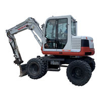
Takeuchi TB175W Workshop Manual (852 pages)
Hydraulic Excavator
Brand:
Takeuchi
| Category:
Excavators
| Size: 53.09 MB
Table of Contents
Contents
3
General Information
6
Table of Contents
6
Safety Precautions
7
Signal Words
7
Appropriate Clothing and Personal Protective Equipment
7
Fire Extinguisher and First Aid Kit
8
Anti-Explosive Lighting
8
Use the Correct Tools
8
Prepare the Work Area
8
Stop the Engine before Performing Maintenance
9
Stay Clear of Moving Parts
9
Securely Block the Machine or any Component that May Fall
9
Secure the Engine Hood or Cover When Opened
9
Cautions on Working on the Machine
10
Use Caution When Fueling
10
Handling of Hoses
10
Be Careful with Hot Cooling Systems
10
Be Careful with Fluids under Pressure
11
Handling of the Accumulator
11
Be Careful with Grease under Pressure
11
Disconnect the Battery
11
Avoid Battery Hazards
12
Safety Signs
12
Disposing of Wastes
12
Tire Maintenance
12
Cautions During Disassembly and Assembly
14
Cautions During Removal and Installation of the Hydraulic Units
14
Cautions During Removal and Installation of Piping
15
Handling of Seals
15
Hydraulic Hoses Tightening Torques
16
Bite Type Pipe Fitting for Steel Pipe Tightening Torques
16
Joints for Piping Tightening Torques
17
Joints for Piping (O-Ring Seal Type) Tightening Torques
17
Bolts and Nuts (for ISO Strength Category 10.9) Tightening Torques
18
Specifications
20
In Regard to Standard Values and Allowable Values
20
Names of Components
21
Machine View
21
Machine Dimensions
22
2-Piece Boom Operating Range
22
Mono-Boom Operating Range
23
Specifications Tables
24
Specifications of Devides
26
Recommended Lubricants
30
Diesel Fuel Standards
31
Standards for Judging Performance
32
Reference Value Table
32
Methods for Inspecting Performance
33
Hydraulic Oil Pressure (Main Relief Valve Set Pressure)
33
Travel, Boom, Arm Measuring Method
33
Travel, Boom, Arm Adjusting Method
33
Dozer Blade Measuring Method
34
Dozer Blade Adjustment Method
34
Hydraulic Oil Pressure (Slewing Relief Valve Set Pressure) Measuring
35
Hydraulic Oil Pressure (Slewing Relief Valve Set Pressure) Adjustment
35
Hydraulic Oil Pressure (Pilot Relief Valve
36
Set Pressure) Measuring
36
Hydraulic Oil Pressure (Pilot Relief Valve Set Pressure) Adjustment
36
Slew Time
37
Overrun When Slewing Stops
37
Natural Slew Drop
37
Boom Cylinder Speed
37
Arm Cylinder Speed
38
Bucket Cylinder Speed
38
Dozer Blade Cylinder Speed
38
Swing Cylinder Speed
38
Adjust Cylinder Speed
39
Natural Cylinder Drop
39
Swing Cylinder
39
Machine Configuration
42
Drive System Construction
43
Engine Mount Exploded View
43
Radiator and Oil Cooler Exploded View
45
Pump Coupling Diagram
46
Fuel Tank and Lines Diagram
47
Fuel Supply Pump Exploded View
48
Slew System Construction
49
Slew Bearing, Slew Motor Diagram
49
Swivel Joint Diagram
50
Travel System Construction
51
Undercarriage Diagram
51
Upper Frame Construction
53
Turntable Diagram
53
Floor Plate Diagram
54
Heater Diagrams
55
Radio Diagram
58
Covers Diagrams
59
Control System Construction
61
Steering Unit Exploded View
61
Able of Connections
63
Control Box R Diagram
64
Control Box L Diagram
64
Dozer Blade Lever Diagram
65
Swing Pedal Diagram
65
Pilot Valve (Brake) Diagram
66
Attachments Construction
67
2-Piece Boom 1 Exploded View
67
2-Piece Boom 2 Exploded View
68
Mono-Boom Exploded View
69
Arm Exploded View
70
Adjusting the Clearance between the Bucket and Arm
71
Hydraulic Circuit Diagram - 2 Piece Boom
73
Hydraulic Circuit Diagram - Mono Boom
74
Hydraulic Tank Diagrams
75
Bleeding the Air
76
Hydraulic Pump
76
Slew Motor
76
Cylinders
76
Electrical Wiring Diagram
77
Electrical System Diagrams
81
Air Conditioner System Construction
85
Compressor Assembly Exploded View
85
Air Conditioner Exploded View
86
Condenser, Air Conditioner Unit, Panel Assembly Diagrams
88
Overview of System Operation
89
Truck and Heavy Equipment Systems
89
Air Conditioner—System Operation
90
Compressor/Clutch Assembly
91
Condenser
92
Receiver-Drier
93
Expansion Valve (Refrigerant Metering Device)
94
Evaporator Coil
94
Heater System Operation
96
Environmental Effects on HVAC System Operation
97
Heater Core
97
Water Valves
97
Defrosters and Ducts, Blowers and Fans
97
Inspection and Maintenance - Without Gauges
99
Inspection & Maintenance Survey Results
99
Visual Inspection - System off
100
Observe the System
100
Inspect Parts
100
Check Hoses and Fittings
102
Check for Refrigerant Leaks
102
Electrical System Inspection
103
Inspect Electrical Connections
103
Check Electrical Current Flow and Device Functions
103
Performance Inspection – Engine Running
105
Inspect System Component Cycling and Cab Temperature Levels
105
Check Clutch Cycling under Load
106
Check Sight Glass
106
Heater System Inspection
107
Check Heater Control Valve Function
107
Preventative Maintenance Worksheet
108
Inspect Other Functions
108
Preventive Maintenance Schedule
110
Troubleshooting and Service Procedures
111
Troubleshooting Overview
111
The Key – Understanding System Function
112
A Troubleshooting Example
113
Manifold Gauge Set Installation
116
Purging Air from Gauge Set Hoses
117
Adding Refrigerant to the System
117
Stabilizing the AC System
119
Troubleshooting by Manifold Gauge Set Readings
120
Low Refrigerant Charge in the System
120
Extremely Low Refrigerant Charge in the System
121
Air And/Or Moisture in the System
122
Excessive Air And/Or Moisture in the System
123
Expansion Valve (TXV) Stuck Closed or Plugged
123
Expansion Valve (TXV) Stuck Open
125
System High Pressure Side Restriction
126
Compressor Malfunction
127
Condenser Malfunction or System Overcharge
128
Thermostatic Switch Malfunction
130
Review of Frequent Problem Areas
131
Belts and Compressor Clutch Problems
131
Condenser Problems
132
Refrigerant Lines, Hoses and Fittings Problems
132
Refrigerant Metering Valves Problems
132
Other Problems — Leaks, Moisture, and Adding Refrigerant
132
Hydraulic Units
136
Hydraulic Pump (Piston) Construction
137
Hydraulic Pump (Piston) Operation
138
Piston Pump
138
Hydraulic Pump Disassembly and Assembly
140
Hydraulic Pump Inspection and Adjustment
148
Hydraulic Pump Troubleshooting
149
Hydraulic Pump (Gear) Construction
151
Gear Pump
151
Gear Pump Disassembly and Assembly
152
Gear Pump Inspection and Adjustment
155
Gear Pump Housing Check
155
Gear Pump Bushing Check
155
Gear Check
156
Seals Check
156
Gear Pump Test Operation
156
Measuring the Discharge Volume (Gear Pump)
157
Control Valve (Mono-Block) Construction
159
Main Relief Valve
165
Port Relief Valve
165
Anti-Drift Valve
165
Control Valve Operation
166
When All Spools Are in the Neutral Positions
166
Center Bypass Passage
166
Signal Passage
166
Control Valve Independent Operation
167
Travel Spool Switching
167
Bucket Spool Switching
167
Boom Spool Switching
168
Swing Spool Switching
169
Arm Spool Switching
170
Compound Operations During Traveling
171
Anti-Drift Valve - Neutral, Raise, Lower
172
Main Relief Valve Relieving Operation
173
Pressure Increase Operation
173
Port Relief Valve Relieving Operation
174
Port Relief Valve Suction Operation
175
Control Valve Disassembly
176
Anti-Drift Valve Disassembly
179
Main Relief Valve Disassembly
180
Control Valve Inspection and Adjustment
181
Control Valve Troubleshooting
182
Control Valves (3-Section/4-Section) Construction
185
Slew Flow Control Section
186
Dozer Blade Section
186
Slew Section
186
Auxiliary Section
187
Outlet Housing
187
Spacer Section
187
Main Relief Valve (3-Section/4-Section)
188
Port Relief Valve (3-Section/4-Section)
188
Control Valves (3-Section/4-Section) Operation
189
When the Spool Is in the Neutral Position
189
When the Spool Is Actuated
189
Load Check Valve
189
Slew Flow Control Function
190
Normal Speed Mode
190
Slow Speed Mode
190
Main Relief Valve/When the Relief Valve Is NOT Operating
191
When the Relief Valve Is Operating
191
Port Relief Valve - Relieving Operation
192
Suction Operation
193
For Auxiliary
193
Control Valves (3-Section/4-Section) Disassembly and Assembly
194
Manually Operated Section
195
Pilot Operated Section
196
Disassembling the Slew Flow Control Block
197
Control Valves (3-Section/4-Section) Inspection and Adjustment
199
Adjusting the Slow Slew Speed Adjusting Valve
200
Solenoid Valves Construction
201
Solenoid Valve (3-Section) - Ram Lock, Lever Lock and Speed Shift
201
Solenoid Valve (3-Section) - Change, Speed Shift and Parking Brake
202
Solenoid Valve (4-Section) - Change and Speed Shift
203
Solenoid Valve Operation
204
When Current Is Not Flowing
204
When Current Is Flowing
204
Solenoid Valves Disassembly and Assembly
205
Solenoid Valve (3-Section) - Ram Lock, Lever Lock and Slew Shift
205
Solenoid Valves Inspection and Adjustment
207
Solenoid Valves Troubleshooting
207
Proportional Control Solenoid Valve Construction
209
Proportional Control Solenoid Valve Operation Principle
210
Proportional Control Solenoid Valve Disassembly and Assembly
211
Proportional Control Solenoid Valve Inspection and Adjustment
212
Proportional Control Solenoid Valve Troubleshooting
212
Selector Valve Construction
213
Swing/Adjust Change
214
Port Relief Valve Construction
215
Port Relief Valve Disassembly and Assembly
216
Shut-Off Valve Construction
217
Shut-Off Valve Operation
218
Shut-Off Valve Inspection and Adjustment
219
Shut-Off Valve Troubleshooting
220
Pilot Valve Construction
221
Pilot Valve Operation
222
When the Handle Is in Neutral
222
When the Handle Is Tilted
222
Pilot Valve Disassembly and Assembly
223
Pilot Valve Inspection and Adjustment
228
Pilot Valve (Swing) Construction
229
Pilot Valve (Swing) Disassembly and Assembly
230
Pilot Valve (Swing) Inspection and Adjustment
232
Pilot Valve (Swing) Troubleshooting
233
Cylinders Construction
235
Boom Cylinder
235
Arm Cylinder
236
Bucket Cylinder
237
Swing Cylinder Diagram
237
Boom Adjustment Cylinder
238
Cylinders Operation
239
Cushion Mechanism
239
Cylinders Disassembly and Assembly
240
Piston Rod Assembly
241
Piston
242
Rod Cover
242
Clevis
242
Cylinders Assembly
243
Cylinders Inspection after Disassembly
246
Piston Rod
246
Tube
246
No Load Operation Test
247
External Leakage
247
Internal Leakage
247
Bleeding Air from the Hydraulic Cylinder
247
Cylinders Troubleshooting
248
Cylinders - Table of Special Tools
249
Installation Jig
249
Sliding Jig
249
Fitting Jig
249
Corrective Jig (E)
250
Dozer Blade Cylinder Construction
251
Ram Lock Cylinder
253
Hydraulic Switching Diagram
254
Start-Up and Bleeding
255
Ram Lock Cylinder - Fault-Finding
255
Ram Lock Cylinder - Repair Instruction
255
Slew Motor Construction
259
Hydraulic Motor Diagram
259
Reduction Gears Diagram
260
Brake Valve Diagrams
261
Hydraulic Motor Operation
262
Relief Valve Operation When the Motor Is Started
262
Relief Valve Operation When the Motor Is Stopped
262
Hydraulic Motor Operation 2
263
Anti-Rebound Valve
263
When the Brake Is Actuated
263
When the Motor Rebounds
263
Timer Valve
264
Parking Brake
264
Reduction Gears
265
Hydraulic Motor Disassembly and Assembly
266
Slew Motor Disassembly
266
Brake Valve and Hydraulic Motor
267
Hydraulic Motor Assembly
274
Slew Motor Inspection and Adjustment
283
Slew Motor Troubleshooting
285
Anit-Rebound Valve Troubleshooting
286
Axle Type: 212 (Front)
287
Index
291
Introduction
293
Classification
293
Specific Equipment and Spare Parts
293
Definition of Viewpoints
295
Date Plate
295
Maintenance Points
295
Maintenance Intervals
296
Adjustment and Checks
296
Conversion Tables
297
Tightening Torques
297
Screw-Locking, Sealing and Lubricating Materials
298
Notes on Safety Precautions
301
Symbols
302
Checking Wear and Replacing the Braking Disks
302
How to Assemble the Braking Units
306
How to Remove the Complete Steering Case
310
How to Assemblye the Complete Steering Case
314
How to Remove the U-Joint
318
Flanged Version
320
Coupling Version
320
Installation of U-Joint
324
How to Disassemble the Planetary Reduction
328
Assembling the Planetary Reduction
336
How to Remove the Steering Cylinder
344
How to Install the Steering Cylinder
348
How to Disassemble the Steering Cylinder
354
How to Assemble the Steering Cylinder
358
How to Remove and Disassemble the Differential Unit
362
How to Assemble and Install the Differential Unit
370
How to Remove the Bevel Pinion
380
How to Install and Adjust the Bevel Pinion
386
Special Tools
398
Troubleshooting
405
How to Disassemble the Mechanic Parking Brake Unit
416
How to Remove and Disassemble the External Hydraulic Negative Brake
424
How to Assemble and Install the External Hydraulic Negative Brake
428
To Disassemble the Ext. Hydraulic Negative Brake with Quick Release
432
Disassembling the Incoming Drum Brake
444
Assembling the Incoming Drum Brake
448
How to Disassemble the 4" Incoming Brake (2 and 3 Function Versions)
452
How to Assemble the 4" Incoming Brake (2 and 3 Function Versions)
462
How to Disassemble the Limited Slip Differential Unit (25% and 45%)
472
How to Assemble the Limited Slip Differential Unit (25% and 45%)
480
How to Disassemble the Hydraulic Differential Lock
484
How to Assemble the Hydraulic Differential Lock
490
How to Disassemble Incorporated Reduction Gear and Pinion
494
How to Assemble Incorporated Reduction Gear and Pinion
504
Axle Type: 112 (Rear)
511
Index (Rear)
515
Introductory Remarks
517
Classification (Rear)
517
Specific Equipment and Spare Parts (Rear)
517
Definition of Viewpoints (Rear)
519
Data Plate (Rear)
519
Maintenance Points (Rear)
519
Maintenance Intervals (Rear)
520
Adjustments and Checks (Rear)
520
Tightening Torques (Rear)
521
Screw-Locking, Sealing and Lubricating Materials (Rear)
522
On Safety Precautions
525
Checking Wear and Replacing the Braking Disks (Rear)
526
How to Assemble the Braking Units (Rear)
530
How to Disassemble the Planetary Reduction and Axle Shaft
534
Notes on Safety Precautions (Axles)
535
Assembling the Planetary Reduction and Axle Shaft
542
How to Remove the Bevel Pinion (Rear)
550
How to Install and Adjust the Bevel Pinion (Rear)
556
Special Tools Diagrams
568
Troubleshooting (Rear)
575
How to Disassemble the Mechanic Parking Brake Unit (Rear)
586
How to Assemble the Mechanic Parking Brake Unit (Rear)
590
To Remove and Disassemble the External Hydraulic Negative Brake
594
To Assemble and Install the External Hydraulic Negative Brake
598
Disassembling the Hydraulic Drum Brake
602
Assembling the Hydraulic Drum Brake
608
How to Disassemble Bevel Pinion Support with Braking Disk
614
How to Assemble Bevel Pinion Support with Braking Disk
618
To Disassemble the 4" Incoming Brake (2 and 3 Function Versions)
620
To Assemble the 4" Incoming Brake (2 and 3 Function Versions)
630
Disassembling the 7" Combined Brake
640
Assembling the 7" Combined Brake
646
To Disassemble the Limited Slip Differential Unit (25% and 45%) (Rear)
654
To Assemble the Limited Slip Differential Unit (25% and 45%) (Rear)
662
How to Disassemble the Hydraulic Differential Lock (Rear)
666
How to Assemble the Hydraulic Differential Lock (Rear)
672
Travel Motor Type: A6VM
676
Type Code
679
Contents (A6VM)
681
Sectional Drawing (A6VM)
682
General Repair Instructions
686
Seal Kits and Sub Assembly Groups
687
Component Groups/Control Components
689
Replace Seal Nut
691
Sealing the Drive Shaft
692
Sealing of the Control Parts
693
Sealing the Hydraulic Control
694
Disassembly of the Port Plate
698
Remove of the Positioning Piston
699
Remove Rotary Group
701
Exchanging of the Rotary Group
703
Inspection Notes
705
Rotary Group Assembly
707
Rotary Group Adjustment
712
Assembly of the Port Plate
713
Tightening Torques (A6VM)
715
Safety Regulations (A6VM)
716
Gear Box Type: 357
718
Index (Gear Box Type 357)
722
Introduction (357)
723
Classification (357)
723
Specific Equipment and Spare Parts (357)
723
Maintenance and Lubricant (357)
725
Tightening Torques (357)
726
Diagrams of Reduction Unit and Exploded Views
727
Reduction Gear (357)
727
1St Gear
728
2Nd Gear
728
Symbols (357)
729
Disassembly of Directly Flanged Reduction Gear 357
729
Removal of Hydralic Gear Control
731
Assembly of Directly Flanged Reduction Gear 357
747
Installation of Hydraulic Gear Control
763
Swivel Joint Type: 532
766
Swivel Joint Type: 532 - Diagrams
768
7-Way Swivel Joint for Hydraulic Applications -
771
Application
771
Principles of Operation
771
Installation Instructions
771
Operation
773
For Replacing the Sealing Rings of Hydraulic Rotary Distributor
775
For Rotary Distributor Top Type
776
General Troubleshooting
778
Cautions in Troubleshooting and Repairs
779
Troubleshooting - Contents
780
Overall Machine Troubleshooting
781
No Operations Can be Done
781
All Operations Can be Done, but There Is no Power
782
The Boom, Bucket, Slew and Arm Do Not Move at All, or the Speed Is Low
784
Slewing Troubleshooting
786
No Slewing Can be Done
786
Right or Left Slewing Cannot be Done
789
Slewing Speed Is Low, or There Is no Power
791
The Machine Slews, but Overrun When Slewing Stops Is Great, or It Cannot be Stopped
793
Slewing in Slow Gear Is Not Possible
795
Boom Troubleshooting
797
The Boom Cylinder Doesn't Move
797
Boom Cylinder Operation Is Slow, or There Is no Power
799
When the Boom Operation Lever Is Pulled Gently, the Boom Drops Temporarily
802
The Amount of Boom Natural Drop Is Great
803
The Boom Adjustment Cylinder Doesn't Move
804
Arm Troubleshooting
807
The Arm Cylinder Doesn't Move
807
Arm Cylinder Operation Is Slow, or There Is no Power
809
The Amount of Arm Natural Drop Is Great
811
Bucket Troubleshooting
812
The Bucket Cylinder Doesn't Move, or There Is no Power
812
The Amount of Bucket Natural Drop Is Great
814
Boom Swing Troubleshooting
815
The Swing Cylinder Doesn't Move
815
Mono Boom Troubleshooting
816
Engine
818
Engine Trouble Diagnostics Tool and Maintenance Tool
819
Machine Maintenance Tool and Trouble Analysis Tool
820
Controller Connection Diagram and System Requirements
821
Machines with Standard Engines
821
Connection Diagram for A25B and A25D
822
Connection Diagram for TL240, TL230, and TL220
823
Connection Diagram for TB180FR
824
Connection Diagram for TB175 and TB175W
825
Connection Diagram for TB1140
826
Connection Diagram for TB175 with an Isuzu Engine
828
USB Cable Connecting the Computer and the Connector on the Machine
829
Isuzu Engine Maintenance Tool
830
Computer Screen after Software Installation
831
Maintenance Software for F14C, F10C and F10B Executed
833
Maintenance Software for A25B and A25D Executed
834
Maintenance Software Is Selected
834
A25B and A25D Maintenance Software for Proportion Output Amplifier
835
F14E Maintenance Software Executed
836
A14E Maintenance Software Is Selected
837
A14EW Maintenance Software Is Selected
837
A25C Maintenance Software Executed
838
Management Software Is Selected
838
Maintenance Software for Proportion Output Amplifier Is Selected
839
Maintenance Tool Executed on the A14E Isuzu Monitor Machine
840
ECM Data Browse Is Selected
841
TB175W Maintenance Software Ver1.0
843
Connecting
843
(System) Open
846
(Device Manager) Open
846
What TB175W Maintenance Software Could Use in COM4
847
Maintenance Software Setting
848
Monitor Error Log
849
Delete Log
849
Save Log
850
Open Saved Log File
850
Print Log
850
See Serial Number of Controller
850
TB175W Maintenance Software Ver1.0, Error Code Table
851
Advertisement
Takeuchi TB175W Operator's Manual (221 pages)
Hydraulic Excavator
Brand:
Takeuchi
| Category:
Excavators
| Size: 5.54 MB
Table of Contents
Table of Contents
7
Introduction
4
Machine Description
6
Table of Contents
7
Safety
10
General Precautions
11
Preparing Precautions
14
Preparing Precautions
15
Starting Precautions
16
Starting Precautions
17
Operating Precautions
18
Operating Precautions
19
Stopping Precautions
25
Transporting Precautions
26
Maintenance Precautions
27
Maintenance Precautions
28
Safety Signs (Decals)
37
Controls
39
Controls
40
Names of Components
40
Doors and Covers
42
Cab Door
42
Seat and Seat Belt
48
Instrument Cluster
50
Control Console
52
Switches
54
Levers and Pedals
59
Levers and Pedals
60
Accessories
63
Cigarette Lighter
66
Operation
71
Operation
72
Before Starting Operation
72
Starting and Stopping the Engine
73
Machine Operation
76
Operating Procedures
86
Parking the Machine
94
Handling in Cold Weather
95
Handling Tires
96
Transport
99
Transport
100
Loading and Unloading
100
Securing the Machine
101
Hoisting the Machine
102
Cautions on Transporting
104
Maintenance
105
Maintenance
106
General
106
Service Data
108
Important Parts
113
Maintenance Chart
114
Walk-Around Inspection
116
Daily Inspection (Every 10 Hours)
118
Inspecting the Water Separator
119
Lubricating the Working Equipment
122
After First 50 Hours
125
(New Machines Only)
125
Every 50 Hours
129
Every 250 Hours
132
Every 400 Hours
135
Every 500 Hours
137
Every 1000 Hours
139
Every 1500 Hours
142
Every 2000 Hours
144
When Required
147
Long-Term Storage
154
Troubleshooting
155
Troubleshooting
156
Symptoms that Are Not Malfunctions
156
If the Engine Overheats
157
If the Battery Goes Dead
158
After the Fuel Runs out
159
If a Fuse Blows
160
If a Warning Lamp Flashes
162
Other Symptoms
164
To Lower the Boom
166
Towing
167
Specifications
169
Specifications
170
Main Specifications
170
Machine Dimensions
172
Operating Range
174
Piece Boom
175
Lifting Capacities
179
Options
185
Options
186
General Precautions
186
Swing Stopper
188
Biodegradable Oil
189
Second Auxiliary Hydraulics
190
Third Auxiliary Hydraulics
192
Fourth Auxiliary Hydraulics
194
Hydraulic Breaker
196
Load Safety Device
198
Fuel Supply Pump
200
Outrigger
201
Air Conditioner
202
Optional Equipment Mass
211
Index
214
Advertisement
Related Products
Takeuchi TB175
Takeuchi TB1160W
Takeuchi TB1140
Takeuchi TB015
Takeuchi TB36
Takeuchi TB285
Takeuchi TB225
Takeuchi TB210R
Takeuchi TB240
Takeuchi TB295W
Takeuchi Categories
Excavators
Compact Excavator
Compact Loader
Tractor
Construction Equipment
More Takeuchi Manuals
Login
Sign In
OR
Sign in with Facebook
Sign in with Google
Upload manual
Upload from disk
Upload from URL