Sign In
Upload
Manuals
Brands
SystemAir Manuals
Air Handlers
DANVENT DV50
SystemAir DANVENT DV50 Manuals
Manuals and User Guides for SystemAir DANVENT DV50. We have
2
SystemAir DANVENT DV50 manuals available for free PDF download: User Manual
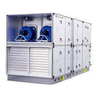
SystemAir DANVENT DV50 User Manual (120 pages)
Without control system
Brand:
SystemAir
| Category:
Air Handlers
| Size: 6.35 MB
Table of Contents
Table of Contents
3
Manufacturer
10
Name Of Machines
10
Declaration Of Conformity - Example
11
General Descriptions, Dangers And Warnings
12
D.1 Overview Via Pictograms on the Inspection Side of the Unit
12
D.1.1 Where Are Pictograms Placed on the Units
13
D.1.2 Label with Production Number
14
D.1.3 Pictogram on a Door for a Fan in a DV Unit
14
D.1.4 Pictograms for All Available Functions in the Units
15
D.1.5 Pictograms about Warnings and Dangers on the Units
17
D.2 Data about the Unit According to Cards and Labels in and on the Unit
18
D.2.1 Machine Card with Unique Data on Every Unit
18
3 Dimensions of the Units
19
D.4 about Operation and Control
19
5 Warnings about Dangers
19
Drawings, Diagrams, Guides and Instructions for the Use, Maintenance and Repair
19
Employees In Charge Of Operation/Control/Maintenance
20
Intended Use And Range Of Applications
20
Unintended Use and Misuse - Inappropriate Applications for the Machine
20
H.1 Air Handling Unit in Operation
20
Instructions for Unloading on the Site as Well as Installation and Connection
21
I.1. Unloading on the Site
21
I.1.1 Unloading by Fork-Lift Truck
21
I.1.2 Unloading by Crane
21
I.1.3 Transport of Unit Without Base Frame on the Site
21
I.1.4 Lifting a Unit with Straps
21
I.1.5 Lifting a Unit with Preinstalled Brackets on the Base Frame for Lifting
22
I.1.6 Roof Unit with Bitumen Roof
22
I.1.7 Roof Unit with Steel Roof
23
I.1.8 Pre-Assembly Storage
23
I.1.9 Tilt Less than 30˚ During Transportation of the Section with Heat Pump - DVU
23
I.2. Installation - Mechanical
23
I.2.1 Free Area in Front of and above the Unit
23
I.2.2 Supporting Surface
23
I.2.3 Adjustable Feet under Legs or Base Frame and Transport of Sections
23
I.2.4 Base Frame Assembly
24
I.2.5 Base Frames for Outdoor Units
25
I.2.6 Installation on the Site of Unit Sections at the Base Frame When Sections Are Delivered on Pallets
25
I.2.7 Joining the AHU Sections
27
I.2.8 Fitting the Ductwork
27
I.2.9 Risk of Stack Effect by Vertical Ducts and Wind Pressure on Louvers
27
I.2.10 Remove Transport Brackets - When Spring Mounts Are Installed
28
I.2.10.1 Impeller Diameters 220 - 560 MM
28
I.2.10.2 Impeller Diameters 630 - 1.000 MM
29
I.2.11 Refitting of Guards
30
I.3. Installation - Electrical
30
I.3.1 Necessary Overvoltage Protection Device, that Leads Lightning Overvoltage to an Earth Lead on a Safe Way
30
I.4 Installation - Pipes for Water - Hot and Chilled, Valves and Drains
30
I.4.1 Description
30
I.4.2 Pipe Connections
31
I.4.3 Possibility of Extracting Components from the Unit
31
I.4.4 Pipe Connections to Batteries
31
I.4.4.1 Heating Coils
31
I.4.4.2 Cooling Coils
31
I.4.4.3 Rigid Pipe Mounting Brackets for Valves, Circulation Pumps and Pipe System
31
I.4.4.3.1 Pipe Connection to Heating Coils
31
I.4.4.3.2 Pipe Connection to Cooling Coils for Chilled Water
32
I.4.5 Draining Condensate Water
33
I.4.6 Draining Condensate Water from Plate Heat Exchanger
33
I.4.7 Draining Condensate Water from Cooling Battery
33
Installation and Assembly Instructions for Reduction of Noise and Vibration Emissions
34
Instructions for Putting into Service, Adjustments, Use and Commissioning
34
K.1 Print-Outs on Paper
34
K.2 Electronic Media
34
K.3 Documentation Is Available for Download from Https://Techdoc.systemair.dk
34
K.4 Start-Up by Installer
34
K.4.1 Checklist, Relevant Values
34
K.4.1.1 Checklist Prior to Start-Up
35
K.4.1.2 Switch on Power
35
K.5 Description of Functions
35
K.5.1 Heating Coil for Hot Water Prepared for Temperature Sensor (Frost Protection)
35
K.5.2 DX Cooling
35
K.5.3 Circulation Pump, Heating
35
K.5.4 Electrical Heater Battery
35
K.5.4.1 Control of Heating Capacity Connected to Unit Without Systemair Control System
35
K.5.5 Speed Control of Fans
36
K.5.5.1 Frequency Converters Inside the Unit Are IP 20
36
K.5.5.2 Frequency Converters on the Unit Are IP 54
36
K.5.6 Pressure Transmitters
36
K.5.7 Damper Motors
36
K.5.8 Filter Guards
36
K.6 Commissioning
36
Information about the Residual Risks that Remain Despite the Inherent Safe Design Measures, Safeguarding and Complementary Protective Measures Adopted
36
L.1 Unit Casing
36
L.1.1. Design of the Machine to Make Transport Safe
36
L.2 Common for All Unit Sections
37
L.2.1 Risk Caused by Surfaces, Edges and Corners
37
L.3 Common for All Unit Sections by Insufficient Lighting
37
L.3.1 Risk Caused by Insufficient Lighting Inside Sections
37
L.4 Dampers Type DVA - DVB - DVM - DVP - Bypass Dampers in DVQ
37
L.4.1 Risk Caused by Maintenance and Cleaning of Dampers
37
L.5 Attenuators Type DVD
37
L.5.1 Risk Caused by Maintenance and Cleaning of Attenuators
38
L.6 Filters Type DVG - DVF
38
L.6.1 Risk Caused by Missing Change of Filters
38
L.6.2 Risk Caused by the Execution of Filter Change
38
L.7 Plug Fans Type DVE
38
L.7.1 Risk Caused by Lightning Strike
38
L.7.2. Risk Caused by Permanent Magnet Motor
39
L.7.3 Risk of Rotating Impeller Caused by Stack Effect (Chimney Effect)
39
L.8 Batteries for Heating and Cooling Type DVR - DVH - DVK - DVU
39
L.8.1 Extreme Temperatures - Heating
39
L.8.2 Extreme Temperatures - Cooling
39
L.9 Heat Pump Units Type DVU
40
L.9.1 Risk of High Temperature
40
L.9.2 Risk Caused by Lightning Strike
40
Instructions on the Protective Measures to be Taken by All Service Technicians During Repair and Maintenance
40
The Essential Characteristics of Tools Which May be Fitted to the Machinery
40
The Conditions of Stability During Use, Transportation, Assembly, Dismantling When out of Service
41
O.1 Installed Reliable to Avoid Units to be Tilted or Moved by the any Storm
41
O.2 Transport of Section with Heat Pump Unit
41
O.3 Disposal of the Heat Pump System - Type DVU
41
O.4 Generel Disassembly - Sharp Edges
41
Instructions for Machinery Where These Are Regularly to be Transported
41
The Operating Method to be Followed in the Event of Breakdown. Safe Restart
41
Adjustment And Maintenance Operations
42
R.1 Shutdown of the Unit to a Safe State
42
R.2 Recommended Maintenance Intervals
43
R.3. Filters - Always Replace Filters with New Filters with the same Characteristics to Maintain SFP Value
45
R.3.1 Bag Filters - the Number of Filters and the Sizes of the Frames
46
R.3.2 Panel Filters - the Number of Filters and the Sizes of the Frames
47
R.3.3 Bag Filters
48
R.3.4 Panel Filters
48
4 Other Functions to Maintain
48
4.1 the Unit
48
4.2 Dampers
49
4.3 Rotary Heat Exchanger DVC
49
4.3.1 Rotor
49
4.3.2 Motor and Belt Drive
50
4.4 Cross Flow and Counter Flow Exchanger
50
4.4.1 By-Pass Damper
50
4.4.2 Condensate Water Drain
50
4.5 Run-Around Heat Exchanger DVR
51
4.5.1 Pump and Pressure Expansion
51
4.5.2 Condensate Water Drain
51
4.6 Heating Coil DVH, Cooling Coil DVK and Change over Coil DVHK
51
4.6.1 Heating Battery
51
4.6.2 Cooling Battery
51
4.6.3 Electeric Heating Battery
52
4.7 Plug Fans DVE
52
4.7.1 Motor
52
4.8 Silencer DVD
52
4.9 Outdoor Air Section DVY
53
4.10 Heat Pump Unit - DVU-HP
54
Instructions Designed to Enable Adjustment and Maintenance to be Carried out Safely, Including the Protective Measures that Should be Taken During These Operations
55
S.1. Protective Measures and Additional Protective Measures
55
S.1.1 Necessary Protection Measures Prior to Start-Up
55
S.1.1.1 Design of Protection Measures
55
S.1.1.2 Configuration of Frequency Converters with Installed Guard
55
S.1.2 Safe Adjustment and Maintenance
55
S.1.3 Personal Protective Equipment for Maintenance Staff - Health and Safety
56
The Specifications of the Spare Parts to be Used, When These Affect the Health and Safety of Operators
56
T.1 Spare Parts - Mechanical
56
T.2 Spare Parts - Electrical
56
Information On Airborne Noise Emissions Exceeding 70 Db(A)
56
Annex For The User Manual
58
Overview Of Annexes
59
Annex 1 Declaration Of Conformity With Unique Production Number
59
Annex 2 Technical Data - Unique Data For Every Unit
59
Annex 3 Spare Part Lists
59
Annex 4 Assemble Base Frames - Height 150 MM For Units In The Sizes 10-40
59
Annex 7 Assemble Base Frames - Height 250 MM For Units In The Sizes
59
Annex 8 Installation Of Steel Roof In The Sizes 10-150
59
Annex 9 Rotary Exchanger - Speed Control and Assembly of Divided Rotor
59
Annex 10 Heat Pump Unit - Dvu-Hp
59
Annex 11 Menu For Internal Controller In The Heat Pump Unit
59
Annex 13 Commissioning Protocol - Proposal (Receipt For Hand-Over)
60
Base Frame Length 720 - 2420 [MM] Unit Size 10-40
62
Base Frame Length 2420 - 4590 [MM] Unit Size 10-40
63
Base Frame Length 4590 - 6200 [MM] Unit Size 10-40
64
Base Frame Length 720 - 2420 [MM] Unit Size 50-DV150
66
Base Frame Length 2420 - 4590 [MM] Unit Size 50-150
67
Base Frame Length 4590 - 6200 [MM] Unit Size 50-150
68
Base Frame Length 720 - 2420 [MM] Unit Size 10-40
70
Base Frame Length 2420 - 4590 [MM] Unit Size 10-40
71
Base Frame Length 4590 - 6200 [MM] Unit Size 10-40
72
Base Frame Length 720 - 2420 [MM] Unit Size 50-150
74
Base Frame Length 2420 - 4590 [MM] Unit Size 50-150
75
Base Frame Length 4590 - 6200 [MM] Unit Size 50-150
76
Overview
77
Mount Rails. Units of Size 30 and Units Larger than Size 30
78
Roof Overhang Along the Long Sides of the Unit
79
Calculation of the Overhang at the Ends of the Unit. Mount Overhang Profile - G1
79
Foam Bands between Rails and Roof Plates - Mount Roof Plates
82
Foam Bands between Roof Plates
82
Mount Roof Plates - some of Them Are Overlapping by 2 Ribs
82
Mount Overhang Profile - G5 on the Other End of the Unit
82
Mount Side Profiles and Corners Along the Edges of the Roof to Protect Persons
83
Apply Sealing on Plate Joints to Ensure Water Resistance
83
Speed Control for Rotor and Assembly of Divided Rotor
85
Speed Control
85
Selection of Correct Signal Via the 8 DIP Switch Levers
85
Indication of Operation Mode Via Red and Green LED as Well as Test of Motor
86
Information about Connection of Cables to Terminals on the Control Board
88
Assemble the Systemair Casing for DV60, DV80, DV100, DV120 Og DV150
90
Assemble Divided Rotor from Hoval Enventus for DV 60, DV 80 and DV 100
94
Tools and Aids
94
Lifting Instruction
95
Installation
96
Installation of Radial Walls
96
Measurement
97
Installation of Rotor Segment and Periphery Plates
98
Installation, First Periphery Plate
99
Installation of Next Segment
100
Installation, Next Periphery Plate
101
Preparation of Segments and Periphery Plates
102
Installation and Adjustment of Brush Sealing
102
Installation of Motor that Turns Rotor and Sensor for Rotation
104
Reversible Heat Pump for Cooling and Heating
107
DVU-HP Section (Reversible Heat Pump Unit)
107
Menu for Internal Controller in the DVU-HP
108
Connection of Fan Motor and Set-Up for Frekv. Conv
109
Connection of Fan Motor
109
Set-Up for Danfoss FC101 for DV-Units with AC Motors
110
AC-Fan Operation Without Thermistor for Danfoss FC101
112
Set-Up Danfoss FC101 for DV-Units with PM Motors
113
Installation Ecblue
116
Connection
116
Residual-Current-Operated Protective Devices
117
Diagnostic/Faults
117
Commissioning
119
Advertisement
SystemAir DANVENT DV50 User Manual (60 pages)
Air Handling Units with control system
Brand:
SystemAir
| Category:
Air Handlers
| Size: 2.07 MB
Table of Contents
Table of Contents
3
Manufacturer
10
B. Name Of Machines
10
C. Declaration Of Conformity - Example
11
D. General Descriptions, Dangers And Warnings
12
D.1 Overview Via Pictograms on the Inspection Side of the Unit
12
D.1.1 Where Are Pictograms Placed on the Units
13
D.1.2 CE Label - Example for DV Unit
14
D.1.3 CE Label - Example for TIME Unit
14
D.1.4 Pictogram on a Door for a Fan in a DV Unit
14
D.1.5 Pictogram on a Door for a Fan in a TIME Unit
14
D.1.6 Pictograms for All Available Functions in the Units
15
D.1.7 Pictograms about Warnings and Dangers on the Units
16
D.2 Data about the Unit According to Cards and Labels in and on the Unit
17
D.2.1 Machine Card with Unique Data on Every Unit
17
D.2.2 Label with Data about the Cabinet
18
D.2.3 Flowchart - Example of the Label Placed on or with the Cabinet
18
D.2.4 Symbols in the Flowchart and Explanation about the Symbols
19
D.2.5 Example of Label Placed on or with the Cabinet - Terminal Plan for External
20
Components
20
D.3 Hand Terminal (Optional for DV Units - Always Standard for TIME Units)
20
D.4 Dimensions of the Units - Selected Examples
21
D.5 Ordinary Automatically Operation - Only Manual Operation by New Parameters
22
D.6 Warnings about Dangers
22
Drawings, Diagrams, Guides and Instructions for the Use, Maintenance and Repair
22
Unintended Use And Misuse - Inappropriate Applications For The Machine
23
23
H.1 Air Handling Unit in Operation
23
Employees In Charge Of Operation/Control/Maintenance
23
F1. Employees That Take Care Of Ordinary Operation
23
Intended Use And Range Of Applications
23
Instructions for Unloading on the Site as Well as Installation and Connection
24
I.1. Unloading on the Site
24
I.1.1 Unloading by Fork-Lift Truck
24
I.1.2 Unloading by Crane
24
I.1.3 Transport of Unit Without Base Frame on the Site
24
I.1.4 Lifting a Unit with Straps
24
I.1.5 Lifting a Unit with Preinstalled Brackets on the Base Frame for Lifting
25
I.1.6 Roof Unit with Bitumen Roof
25
I.1.7 Roof Unit with Steel Roof
25
I.1.8 Pre-Assembly Storage
26
I.1.9 Tilt Less than 30˚ During Transportation of the Section with Cooling Compressor - DVU or DVU-C
26
I.2. Installation - Mechanical
26
I.2.1 Free Area in Front of and above the Unit
26
I.2.2 Supporting Surface
26
I.2.3 Adjustable Feet under Legs or Base Frame and Transport of Sections
26
I.2.4 Base Frame Assembly
26
I.2.5 Base Frames for Outdoor Units
27
I.2.6 Installation on the Site of Unit Sections at the Base Frame When Sections Are Delivered on Pallets
27
I.2.7 Joining the AHU Sections
29
I.2.8 Fitting the Ductwork
30
I.2.9 Risk of Stack Effect by Vertical Ducts and Wind Pressure on Louvers
30
I.2.10 Refitting of Guards
30
I.3. Installation - Electrical
31
I.3.1 Description
31
I.3.2 Wiring Diagrams
31
I.3.2.1 TIME Units - Labels on the Cabinet Next to the Supply Fan
31
I.3.2.2 DV Units - Labels on or with the Cabinet
31
I.3.3 Installation of Mains Power Supply
31
I.3.3.1 Necessary Mains Power Supply for TIME Units with Ec Motors and Without DVU
31
I.3.3.2 Necessary Mains Power Supply for DV Units with Cabinet/Control System
32
I.3.3.3 Necessary Overvoltage Protection Device, that Leads Lightning Overvoltage to an Earth Lead on a Safe Way
32
I.3.4 Electrical Connection of Components and Functions
32
I.3.4.1 Connection of the Systemair Control Panel to the Corrigo E28 Controller - Software Version 3.3
32
I.4 Installation - Pipes for Water - Hot and Chilled, Valves and Drains
33
I.4.1 Description
33
I.4.2 Pipe Connections
33
I.4.3 Possibility of Extracting Components from the Unit
33
I.4.4 Pipe Connections to Batteries
33
I.4.4.1 Heating Coils
33
I.4.4.2 Cooling Coils
34
I.4.4.3 Rigid Bearings for Valves, Circulation Pumps and Pipe System
34
I.4.4.3.1 Pipe Connection to Heating Coils
34
I.4.4.3.2 Pipe Connection to Cooling Coils for Chilled Water
35
I.4.4.3.3 Valve Motor and Valve for Heating
35
I.4.4.3.4 Valve Motor and Valve for Cooling
35
I.4.5 Draining Condensate Water
35
I.4.6 Draining Condensate Water from Plate Heat Exchanger
36
I.4.7 Draining Condensate Water from Cooling Battery
36
Installation and Assembly Instructions for Reduction of Noise and Vibration Emissions
36
Instructions for Putting into Service, Adjustments, Use and Commissioning
37
K.1 Print-Outs on Paper
37
K.2 Electronic Media
37
K.3 Documentation Is Available for Download from Https://Techdoc.systemair.dk
38
K.4 Start-Up by Installer
38
K.4.1 Checklist, Relevant Values
38
K.4.1.1 Checklist Prior to Start-Up
38
K.4.1.2 Switch on Power
38
K.5 Adjustments and Use
38
K.6 Description of Functions
38
K.6.1 Remote Control
38
K.6.1.1 Communication WEB-Master (TCP/IP Exoline) to PC and Android Telephone
38
K.6.1.2 Communication to BMS Systems with MODBUS
39
K.6.1.3 Communication to BMS Systems with LON
39
K.6.1.4 Communication to BMS Systems Via Bacnet
39
K.6.2 Extended Operation and External Start/Stop (for Example by Presence Detectors)
39
K.6.3 Valve and Valve Motor for Heating Coil
39
K.6.4 Valve and Valve Motor for Cooling Coil
39
K.6.5 DX Cooling
39
K.6.6 Circulation Pump, Heating
39
K.6.7 Fire Alarm Function
40
K.6.7.1 External Fire Signal that Indicate Block or Run
40
K.6.7.2 External Fire Signal
40
K.6.7.3 Two Fire Thermostats
40
K.6.7.4 One Smoke Detector in Extract Air
40
K.6.8 E Tool - Configuration Tool
40
K.6.9 Electrical Heater Battery
40
K.6.9.1 Control of Heating Capacity Connected to Unit with Systemair Control System
40
K.6.9.2 Control of Heating Capacity Connected to Unit Without Systemair Control System
40
K.6.10 Speed Control of Fans
41
K.6.10.1 TIME Control System - EC Motors
41
K.6.10.2 DV Control System - Frequency Converters Inside the Unit Are IP 20
41
K.6.10.3 Pressure Transmitters
41
K.6.10.4 CO2-Dependent Air Flow
41
K.6.10.5 Humidity Dependent Air Flow
41
K.6.11 Cabinet
41
K.6.11.1 Integrated Cabinets in TIME Units
41
K.6.11.2 Integrated Cabinet in DV Units with Control System
41
K.6.11.3 Cabinet Placed on the DV Unit with Control System
41
K.6.13 Damper Motors
42
K.6.14 Filter Guards
42
K.6.15 Room Temperature Sensors
42
K.6.16 Frost Protection
42
K.6.17 Systemair Control Panel - SCP
42
K.6.18 Cooling Recovery
42
K.6.19 Free Cooling
42
K.6.20 Alarm Signal
43
K.6.21 Heat Recovery
43
K.6.22 Frost Protection - Plate Heat Exchanger
43
K.7 Commissioning
43
Information about the Residual Risks that Remain Despite the Inherent Safe Design Measures, Safeguarding and Complementary Protective Measures Adopted
43
L.1 Unit Casing
43
L.1.1. Design of the Machine to Make Transport Safe
43
L.2 Common for All Unit Sections
43
L.2.1 Risk Caused by Surfaces, Edges and Corners
43
L.3 Common for All Unit Sections by Insufficient Lighting
44
L.3.1 Risk Caused by Insufficient Lighting Inside Sections
44
L.4 Dampers Type DVA - DVB - DVM - DVP - Bypass Dampers in DVQ
44
L.4.1 Risk Caused by Maintenance and Cleaning of Dampers
44
L.5 Attenuators Type DVD
44
L.5.1 Risk Caused by Maintenance and Cleaning of Attenuators
44
L.6 Filters Type DVG - DVF
44
L.6.1 Risk Caused by Missing Change of Filters
44
L.6.2 Risk Caused by the Execution of Filter Change
45
L.7 Plug Fans Type DVE
45
L.7.1 Risk Caused by Lightning Strike
45
L.7.2. Risk Caused by Permanent Magnet Motor
45
L.7.3 Risk of Rotating Impeller Caused by Stack Effect (Chimney Effect)
45
L.8 Batteries for Heating and Cooling Type DVR - DVH - DVK, Cooling Compressor
46
L.8.1 Extreme Temperatures - Heating
46
L.8.2 Extreme Temperatures - Cooling
46
L.9 Cooling Compressor Units Type DVU - DVU-C
46
L.9.1 Risk of High Temperature
46
L.9.2 Risk Caused by Lightning Strike
46
Instructions on the Protective Measures to be Taken by All Service Technicians During Repair and Maintenance
46
The Essential Characteristics of Tools Which May be Fitted to the Machinery
47
The Conditions of Stability During Use, Transportation, Assembly, Dismantling When out of Service
47
O.1 Installed Reliable to Avoid Units to be Tilted or Moved by the any Storm
47
O.2 Transport of Section with Cooling Compressor Unit
47
O.3 Disposal of the Cooling Compressor System - Type DVU and DVU-C
47
O.4 Generel Disassembly - Sharp Edges
47
P. Instructions For Machinery Where These Are Regularly To Be Transported
48
The Operating Method to be Followed in the Event of Breakdown. Safe Restart
48
Adjustment And Maintenance Operations
48
R.1 Shutdown of the Unit to a Safe State
48
R.2 Recommended Maintenance Intervals
49
R.3. Filters - Sizes and Numbers
50
R.3.1 Bag Filters
51
R.3.2 Panel Filters
51
R.4. Changing the Internal Battery in the Controller
51
R.5 Other Functions to Maintain
52
R.5.1 the Unit
52
R.5.2 Dampers
52
R.5.3 Rotary Heat Exchanger DVC
53
R.5.3.1 Rotor
53
R.5.3.2 Motor and Belt Drive
53
R.5.4 Cross Flow and Counter Flow Exchanger
53
R.5.4.1 By-Pass Damper
54
R.5.4.2 Condensate Water Drain
54
R.5.5 Run-Around Heat Exchanger DVR
54
R.5.5.1 Pump and Pressure Expansion
54
R.5.5.2 Condensate Water Drain
54
R.5.6 Heating Coil DVH, Cooling Coil DVK and Change over Coil DVHK
55
R.5.6.1 Heating Battery
55
R.5.6.2 Cooling Battery
55
R.5.6.3 Electeric Heating Battery
55
R.5.7 Plug Fans DVE
55
R.5.7.1 Motor
55
R.5.8 Silencer DVD
55
R.5.9 Outdoor Air Section DVY
56
R.5.10 Cooling Compressor Units DVU and DVU-C
56
R.5.10.1 Cooling Compressor Circuit
57
R.5.10.2 Built-In Control System
57
R.5.10.3 Maintenance of Built-In Control System
57
Instructions Designed to Enable Adjustment and Maintenance to be Carried out Safely, Including the Protective Measures that Should be Taken During These Operations
57
S.1. Protective Measures and Additional Protective Measures
57
S.1.1 Necessary Protection Measures Prior to Start-Up
58
S.1.1.1 Design of Protection Measures
58
S.1.1.2 Configuration of Frequency Converters with Installed Guard
58
S.1.2 Safe Adjustment and Maintenance
58
S.1.3 Personal Protective Equipment for Maintenance Staff - Health and Safety
58
The Specifications of the Spare Parts to be Used, When These Affect the Health and Safety of Operators
59
T.1 Spare Parts - Mechanical
59
T.2 Spare Parts - Electrical
59
Information On Airborne Noise Emissions Exceeding 70 Db(A)
59
Annex 1 Declaration Of Conformity With Unique Production Number
59
Advertisement
Related Products
SystemAir Danvent DV-10
SystemAir Danvent DV-20
SystemAir Danvent DV-30
SystemAir DANVENT DV80
SystemAir DANVENT DV100
SystemAir DANVENT DV120
SystemAir DVV-XS
SystemAir DVVI-XS
SystemAir DVVI Series
SystemAir DVV/F600
SystemAir Categories
Fan
Air Handlers
Ventilation Hood
Air Conditioner
Fire and Smoke Dampers
More SystemAir Manuals
Login
Sign In
OR
Sign in with Facebook
Sign in with Google
Upload manual
Upload from disk
Upload from URL