Sign In
Upload
Manuals
Brands
Suzuki Manuals
Motorcycle
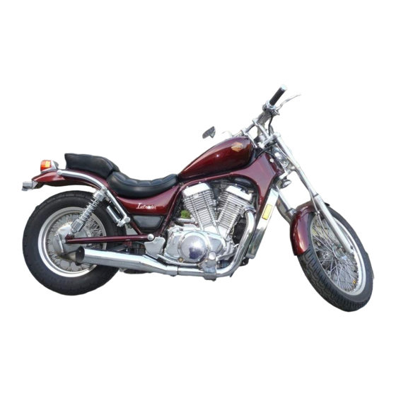
Intruder VS700
Suzuki Intruder VS700 Manuals
Manuals and User Guides for Suzuki Intruder VS700. We have
1
Suzuki Intruder VS700 manual available for free PDF download: Service Manual
Suzuki Intruder VS700 Service Manual (527 pages)
Brand:
Suzuki
| Category:
Motorcycle
| Size: 170.9 MB
Table of Contents
Engine
2
View of Suzuki VS700GLP
4
View of Suzuki VS700GLF
4
Group Index
5
Table of Contents
6
Supplements
6
General Information
7
Serial Number Locations
8
Fuel
8
Engine Oil
8
Gear Oil (Final Drive)
8
Anti-Freeze/Coolant
9
Breaking-In Procedures
9
Coolant
9
Cylinder Identification
9
Special Materials
10
Precautions and General Instructions
12
Replacement Parts
12
Specifications
13
Dimensions and Dry Mass
13
Engine
13
Chassis
13
Periodic Maintenance and Tune-Up Procedures
14
Periodic Maintenance Schedule
15
Periodic Maintenance Chart
15
Lubrication Point
16
Maintenance and Tune-Up Procedures
17
Battery
17
Air Cleaner
18
Front Side Air Cleaner
18
Rear Side Air Cleaner
18
Valve Clearance
19
Valve Clearance Specifications
19
Inspection of the Rear Side Valve Clearance
20
Spark Plug
21
Engine Oil and Oil Filter
22
Necessary Amount of Engine Oil
22
Carburetor
23
Throttle Cable Play
23
Fuel and Vapor Hose
23
Clutch
24
Clutch Fluid Level
24
Bleeding Air from the Clutch Fluid
24
Cooling System
25
Coolant Capacity
25
Brake Fluid Level
26
Front Brake
26
Brakes
26
Final Gear Oil
26
Brake Pads
27
Bleeding Air from the Brake Fluid Circuit
27
Bleeder Valve Tightening Torque
27
Rear Brake
28
Front Brake Light Switch
28
Brake Pedal Height and Free Travel
28
Brake Light Switch
28
Brake Shoe Wear
29
Tire Pressure
29
Tire Tread Condition
29
Tires
29
Steering
30
Front Fork
30
Chassis Bolts and Nuts
31
Compression Check
34
Compression
34
Compression Test Procedure
34
Engine Components Removable with the Engine in Place
35
Engine Removal
36
Engine Reinstallation
42
Tightening Torque
43
Engine Disassembly
44
Bearing and Oil Seal (Except for Crankshaft)
59
Drive Gear
60
Driven Gear
61
Cooling System Relation Part
62
Engine Components Inspection and Servicing
63
Cylinder Head Cover Disassembly
63
Cylinder Head Cover Distortion
63
Rocker Arm Shaft O.D.
63
Rocker Arm I.D.
64
Camshaft
64
Cam Chain 20-Pitch Length
65
Cam Chain Tensioner
65
Cam Chain Guide
65
Camshaft Cam Wear
65
Camshaft Journal Wear
66
Camshaft Journal Oil Clearance
66
Cylinder Head Cover Tightening Torque
66
Camshaft Runout
67
Cylinder Head Disassembly
67
Cylinder Head Distirtion
67
Valve Face Wear
68
Valve Stem Runout
68
Valve Head Radial Runout
68
Valve Guide Servicing
69
Valve Stem Wear
69
Valve Guide - Valve Stem Clearance
69
Valve Seat Width
71
Valve Seat Servicing
71
Parts List of Valve Seat Servicing Tools
71
Valve Stem End Condition
73
Valve Springs (Refer to Service Data)
73
Valve Spring Free Length Limit
73
Valve Spring Tension
73
Cylinder Bore
74
Cylinder Distortion
74
Reassembly
74
Piston Diameter
75
Piston-Cylinder Clearance
75
Piston Ring-Groove Clearance
75
Piston Ring
76
Free End Gap and End Gap
76
Piston Ring Groove Width
76
Piston Ring Thickness
76
Piston Pin and Pin Bore
77
Oversize Piston Rings
77
Oversize Oil Rings
77
Oversize Side Rail
77
Connecting Rod Big End Thrust Clearance
78
Connecting Rod Small End Bore I.D.
78
Connecting Rod - Crank Pin Bearing Selection
79
Bearing Selection Table
80
Oil Clearance
80
Connecting Rod I.D. Specification
80
Crank Pin O.D. Specification
80
Bearing Assembly
81
Bearing Thickness
81
Crankshaft
82
Crankcase-Crankshaft Bearing Selection
82
Crankshaft Thrust Clearance
83
Clutch Drive Plates and Driven Plates
84
Clutch Cylinder
85
Clutch Spring Free Length
85
Clutch Bearings
85
Clutch Reassembly
86
Generator and Signal Generator
86
Starter Clutch
86
Oil Pump
88
Transmission Gears and Related Parts
88
Gear-Shifting Fork Clearance
89
Countershaft Reassembly
89
Shift Fork - Groove Clearance
89
Shift Forks Groove Width
89
Driveshaft Reassembly
90
Engine Reassembly
91
Camshaft Timing
106
Valve Rocker Arm and Shaft
109
Cylinder Head Bolt
110
Cylinder Head Cover Bolt
110
Shaft Drive
111
Secondary Bevel Gears Construction
113
Shaft Drive Removal and Disassembly
114
Secondary Drive Bevel Gear
114
Secondary Driven Bevel Gear
114
Shaft Drive Inspection
115
Shaft Drive Reassembly
115
Backlash
116
Secondary Gears Shim Adjustment
116
Tooth Contact
117
Reassembly Information
118
Final Vebel Gears Construction
119
Final Gear Case Breather Circuit
120
Air and Gear Oil Flow in Final Gear Case Breather Circuit
120
Air Passage
120
Oil Passage
120
Final Gear Case Removal and Disassembly
121
Propeller Shaft Removal and Disassembly
121
Driven Bevel Gear Removal and Disassembly
121
Drive Bevel Gear Removal and Disassembly
123
Final Gear Case and Bearing Case
126
Final Gear Shim Adjustment
128
Final Gear Bearing Case Shim Clearance
128
Final Assembly and Remounting
131
Cooling System Description
136
Cooling Solution
137
Anti-Leakage Material
137
Coolant Density Boiling Point Curve
137
Coolant Density-Freezing Point Curve
137
Radiator and Water Hoses Removal
138
Radiator and Water Hoses Inspection
138
Thermostat Inspection
139
Radiator and Water Hoses Installation
139
Thermostat Removal
139
Radiator Hose
139
Water Pump Removal
141
Water Pump Disassembly
142
Water Pump Inspection
144
Water Pump Reassembly
144
Thermo-Switch Inspection
145
Engine Thermo-Switch
145
Thermo-Switch Specification
145
Thermo-Switch Tightening Torque
145
Coolant Temperature Gauge Reassembly
146
Coolant Temperature Gauge Inspection
146
Coolant Temperature Gauge Removal
146
Fan Motor
146
Fuel and Lubrication System
147
Fuel System
148
Fuel System Description
149
Fuel Cock
149
Starting Engine
149
After Start
149
Fuel Pump
150
Fuel Pump Relay
151
No.2 Front Carburetor
152
Carburetor Construction
152
No.1 Rear Carburetor
153
I.D. No. Location
154
Diaphragm and Piston Operation
155
Slow System
156
Transient Enrichment System
156
Main System
157
Starter System
158
Float System
158
Needle Valve Inspection
165
Float Height Adjustment
165
Fuel Level Inspection
167
In Case of Changing the Synchronizing Cable
168
Balancing Carburetors
168
In Case of Changing the Throttle Cable
170
In Case of Changing the Carburetors
170
Lubrication System
171
Oil Pressure
171
Oil Sump Filter
171
Oil Pressure Specification
171
Lubrication System Chart
172
Emission Control Informations
174
Emission Control Carburetor Components
175
Electrical System
176
Function of Regulator
177
Charging System Description
177
Charging Output Check
179
AC Generator No-Load Performance
179
AC Generator Continuity Check
180
Regulator/Rectifier
180
Ignition System Description
181
Ignition Coils Inspection
181
Signal Generator
182
Ignitor Unit
183
Starter System Description
184
Starter Motor Removal and Disassembly
184
Commutator
185
Carbon Brushes
185
Starter Motor Inspection
185
O-Ring
186
Armature Coil
186
Starter Motor Reassembly
186
Oil Seal
186
Starter Relay Inspection
187
Housing Screw
187
Speedometer and Instrument Panel Removal and Disassembly
188
Speedometer and Instrument Panel Inspection
188
Water Temperature Unit and Indicator Inspection
190
Tail/Brake Light
191
Headlight
191
Lamps
191
Turn Signal Light
192
Ignition Switch
192
Switches
192
Dimmer Switch
193
Turn Signal Switch
193
Horn Switch
193
Engine Stop and Start Switch
193
Clutch Switch
194
Front Brake Switch
194
Neutral Indicator Switch
194
Rear Brake Switch
194
Wire Color
195
Side Stand Check Switch
195
Oil Pressure Switch
195
Battery Remounting
196
Battery Removal
196
Battery Specifications
197
Battery Initial Charging
197
Battery Servicing
197
Filling Electrolyte
197
Recharging Operation Based on S.G. Reading
198
Service Life
199
Front Wheel Construction
201
Front Wheel Removal and Disassembly
201
Wheel Bearings Inspection
202
Brake Disc
202
Wheel Bearing
202
Axle Shaft Inspection
203
Wheel Rim Inspection
203
Spoke Nipple Inspection
203
Tire Inspection
203
Wheel Bearing Reassembly
204
Brake Pad Replacement
206
Caliper Removal and Disassembly
206
Caliper and Disc Inspection
208
Caliper Reassembly
209
Master Cylinder Removal and Disassembly
209
Master Cylinder Inspection
211
Master Cylinder Reassembly
212
Front Fork Removal
212
Master Cylinder Disassembly
213
Fork Spring Inspection
215
Inner Tube and Outer Tube Inspection
215
Damper Rod Ring
216
Inner Tube Metal Reassembly
216
Oil Lock Piece Reassembly
216
Damper Rod Bolt Reassembly
216
Fork Spring
217
Fork Oil
217
Outer Tube Metal, Oil Seal and Dust Seal
217
Inner Tube
218
Steering Stem Construction
218
Steering Stem Disassembly
218
Outer Races Reassembly
221
Bearing Reassembly
221
Stem Nut
222
Handlebar Holder
222
Handlebars
223
Rear Wheel and Brake Construction
223
Brake Shoe
226
Wheel Damper
227
Brake Drum
227
Brake Rod Link Removal and Disassembly
230
Brake Rod Link Inspection
231
Brake Rod Link Remounting and Reassembly
232
Rear Suspension and Swingarm Removal
233
Dust Seal
236
Rear Shock Absorber
236
Swingarm Bearing Reassembly
236
Clutch Master Cylinder
237
Clutch Master Cylinder Removal and Disassembly
238
Servicing Information
241
Engine Troubleshooting
242
Shaft Drive Troubleshooting
244
Carburetor Troubleshooting
245
Radiator Troubleshooting
246
Electrical Troubleshooting
246
Battery Troubleshooting
247
Chassis Troubleshooting
248
Brakes Troubleshooting
249
Wiring Diagram
250
Cable, Harness and Hose Routing
251
Front Brake Hose Routing
254
Clutch Hose Routing
255
Vapor Hose Routing
256
Periodic Maintenance
256
Service Data
256
Maintenance Chart
256
Special Tools
257
Engine Tightening Torque
262
Cooling Tightening Torque
263
Shaft Drive Tightening Torque
263
Chassis Tightening Torque
263
Tightening Torque Chart
264
Valve + Guide Service Data
265
Camshaft + Cylinder Data Service Data
265
Cylinder + Piston + Piston Ring Service Data
266
Conrod + Crankshaft Service Data
267
Oil Pump Service Data
267
Clutch Service Data
268
Transmission Service Data
268
Shaft Drive Service Data
269
Carburetor Service Data
269
Electrical Service Data
269
Wattage Service Data
270
Brake + Wheel Service Data
270
Suspension Service Data
271
Tire Pressure Service Data
271
Thermostat + Radiator + Fan Service Data
272
Fuel + Oil Service Data
272
Vs700Gle
273
View of VS700GLE
274
VS700GLE Specifications
275
VS700GLE Periodic Maintenance Schedule
277
VS700GLE Periodic Maintenance Chart
277
VS700GLE Lubrication Point
278
VS700GLE Maintenance and Tune-Up Procedure
279
VS700GLE Battery
279
VS700GLE Engine and Oil Filter
280
View of Suzuki VS700GLH
295
Right Side
319
Left Side
319
View of Suzuki VS750GLJ
319
View of Suzuki VS800GLN
364
Chassis
457
Vs800Gly/K1/K2/K3 ('00/'01/'02/'03-Model)
458
Steering Stem
469
Cable Routing
470
Vs800Glk4 ('04-Model)
471
Vs800K5 ('05-Model)
483
Service Data
485
Wiring Harness Routing
494
Clutch Hose Routing
495
Front Brake Hose Routing
496
Handle Balancer Installation
496
Tool Holder Installation
496
Evaporative Emission Control System (for E-33)
497
Wiring Diagram
498
Vs800K6 ('06-Model)
499
Vs800K7 ('07-Model)
512
Air Cleaner
513
Clutch
517
Primary Reduction Ratio
517
2Nd
517
3Rd
517
4Th
517
Top
517
Secondary Reduction Ratio
517
Electrical
519
Spark Plug
519
Battery
519
Headlight
519
Turn Signal Light
520
Brake Light/Taillight
520
License Plate Light
520
Neutral Indicator Light
520
High Beam Indicator Light
520
Turn Signal Indicator Light
520
Oil Pressure Indicator Light
520
Speedometer Light
520
L (3.2/2.6 Us/Imp Gal)
522
Vs800K8 ('08-Model)
523
Advertisement
Advertisement
Related Products
Suzuki Intruder VS1400
Suzuki VS750
Suzuki Intruder VS800
Suzuki V Storm
Suzuki Vstrom
Suzuki Vstrom DL650 K4
Suzuki Vstrom DL650A K9
Suzuki Vstrom DL1000 K9
Suzuki Intruder VS600GL
Suzuki V-STROM 800
Suzuki Categories
Motorcycle
Automobile
Motorcycle Accessories
Musical Instrument
Offroad Vehicle
More Suzuki Manuals
Login
Sign In
OR
Sign in with Facebook
Sign in with Google
Upload manual
Upload from disk
Upload from URL