Sign In
Upload
Manuals
Brands
Suzuki Manuals
Motorcycle
GSF 400 BANDIT
Suzuki GSF 400 BANDIT Naked Sport Bike Manuals
Manuals and User Guides for Suzuki GSF 400 BANDIT Naked Sport Bike. We have
1
Suzuki GSF 400 BANDIT Naked Sport Bike manual available for free PDF download: Service Manual
Suzuki GSF 400 BANDIT Service Manual (272 pages)
Brand:
Suzuki
| Category:
Motorcycle
| Size: 64.12 MB
Table of Contents
Index
2
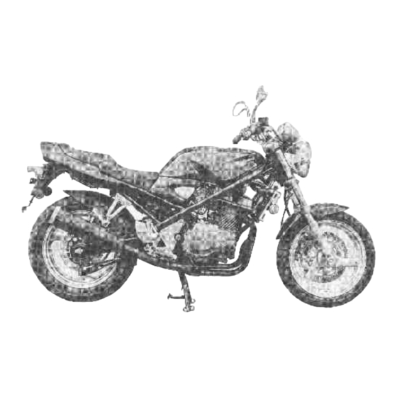
View of Suzuki Gsf400/Bandit
3
General Information
4
Serial Number Location
5
Fuel, Oil and Coolant Recommendation
5
Engine Oil Recommendation
6
Brake Fluid Recommedation
6
Front Fork Oil Recommendation
6
Coolant/Water for Mixing/Anti-Freeze Recommendation
6
Liquid Amount of Water/Coolant
7
Break-In Procedures
7
Cylinder Identification
7
Special Materials
8
Precautions and General Instructions
11
Replacement Parts
11
Asbestos Information
12
Specifications
13
Country or Area Symbols
15
Exterior Parts Removal
16
Seats Removal
16
Frame Covers Removal
16
Air Cleaner Side Covers Removal
16
Periodic Maintenance and Tune-Up Procedures
17
Periodic Maintenance Schedule
18
Lubrication Points
19
Maintenance and Tune-Up Procedures
20
Battery Maintenance
20
Cylinder Head Nuts and Exhaust Pipe Bolts Maintenance
20
Exhaust Pipe and Muffler Maintenance
21
Air Cleaner Maintenance
21
Valve Clearance Maintenance
22
Spark Plugs Maintenance
24
Engine Oil and Oil Filter Maintenance
25
Necessary Amout of Engine Oil
25
Fuel Line Maintenance
25
Carburetors Maintenance
26
Engine Idling Speed
26
Throttle Cable Play
26
Cooling System/Coolant Level
26
Clutch Maintenance
27
Coolant Change
27
Drive Chain Maintenance
28
Drive Chain Checking/Adjusting/Cleaning/Lubricating
29
Brake Fluid Level Check
30
Brake Pads Check
30
Brake Pedal Height
31
Brake Light Switches Adjustment
31
Air Bleeding the Brake Fluid Circuit
31
Tires Maintenance
32
Tire Tread Condition
32
Steering Maintenance
33
Tire Pressure
33
Front Forks Check
34
Rear Suspension Check
34
Chassis Bolts and Nuts Check
35
Engine
37
Compression Pressure Check
38
Compression Test Procedure
38
Oil Pressure Check/Test Procedure
39
Engine Components Removable with Engine in Place
40
Engine Center
40
Engine Removal
41
Engine Reinstallation
45
Engine Disassembly
47
Engine Components Inspection and Service
57
Cylinder Head Inspection
57
Cylinder Head Distortion Check
58
Valve Stem Runout Check
58
Valve Head Radial Runout Check
58
Valve Race Wear Check
59
Valve Stem Deflection/Wear Check
59
Valve Guide Servicing
59
Valve Seat Width/Servicing
60
Valve Stem End Condition
62
Valve Springs
62
Valve Reassembly
63
Camshaft
64
Cam Wear
65
Camshaft Journal Wear
65
Camshaft Runout
66
Cam Sprocket
66
Camshaft Reassembly
66
Cam Chain Tensioner/20-Pitch Length
67
Cam Chain Guide
67
Cylinder Distortion/Bore
67
Piston Diameter
68
Piston-Cylinder Clearance
68
Piston Ring-Groove Clearance
68
Piston Ring Free End Gap and Piston Ring End Gap
69
Piston Pin and Pin Bore
69
Conrod Small End ID/Big End Side Clearance
70
Conrod-Crank Pin Bearing Selection
70
Conrod ID Specification
72
Crank Pin OD Specification
72
Bearing Thickness
72
Bearins Assembly
72
Crankcase-Crankshaft Bearing Selection
73
Bearing Selection Table
74
Crankcase ID Specification
74
Crankshaft Journal OD Specification
74
Crankshaft Thrust Clearance
75
Crankshaft Runout
76
Thrust Bearing Selection Table
76
Clutch Drive and Driven Plates
77
Clutch Spring Free Length
77
Clutch Release Bearing
77
Oil Pump
78
Transmission Diagram
78
Transmission Disassembly
78
Transmission Reassembly
79
Gearshift Fork-Groove Clearance
80
Engine Reassembly
81
Clutch Diagram
87
Breather Cover Servicing
99
Fuel and Lubrication System
100
Fuel System
101
Fuel Tank and Fuel Cock Removal
102
Fuel Cock Inspection/Cleaning
102
Carburetor Diagram and Parts List
103
Carburetor Specifications
104
ID no Location
105
Diaphragm and Piston Operation
106
Slow System
107
Main System
108
Starter System
109
Float System
109
Carburetor Inspection and Asjustment
110
Needle Valve Inspection
110
Float Height Adjustment
110
Reassembly and Remounting
110
Balance of Carburetors
111
Calibrating each Gauge
111
Balancing Carburetors
112
Lubrication System
113
Oil Sump Filter
113
Lubrication System Chart
114
Cooling System
115
Cooling System Description
116
Cooling System Diagram and Parts List
117
Cooling Solution
119
Cooling System Removal and Disassembly
120
Radiator Removal
120
Cooling Fan Removal
121
Water Thermo-Switch and Cooling Fan Thermo-Switch Removal
121
Thermostat Removal
122
Water Pump Removal
122
Radiator Inspection/Installation
124
Water Thermo-Switch Inspection/Reassembly
125
Cooling Fan Inspection
125
Cooling Fan Thermo-Switch Inspection/Reassembly
126
Thermostat Inspection/Reassembly
127
Water Pump Inspection/Reassembly
128
Electrical System
130
Charging System Description
131
Function of Regulator
131
Electrical System Inspection
133
Charging Output Check
133
AC Generator No-Load Performance/Continuity Check
133
Regulator/Rectifier Check
134
Ignition System (Digital Ignitor) Description
135
Ignition System Inspection
136
Ignition Coil Checking with Electro Tester
136
Signal Generator Checking with Pocket Tester
136
Spark Plug Check/Recommended Spark Plug
137
Ignitor Unit Checking
138
Starter System Description/Removal/Disassembly
140
Starter System Inspection
141
Carbon Brush Check
141
Commutator Check
141
Armature Coil Check
142
Oil Seal Check
142
Starter System Reassembly
142
Starter Relay Inspection
143
Side-Stand/Ignition Interlock System Description
143
Side-Stand/Ignition Interlock System Inspection
145
Diode Check
145
Neutral Switch Check
145
Side-Stand/Ignition Interlock Relay Check
145
Combination Meter Removal and Disassembly
146
Combination Meter Inspection
147
Lamps: Headlight/Tail/Brake Light Diagrams
148
Turn Signal Light Diagram
149
Switches
149
Oil Pressure Switch
149
Turn Signal Relay
150
Battery Specifications
151
Battery Initial Charging
151
Battery Servicing
152
Battery Recharging Operation
153
Chassis
154
Front Wheel Diagram/Removal
155
Wheel Bearings Inspection
156
Axle Shaft Inspection
156
Wheel Inspection
156
Wheel Reassembly and Remounting
157
Brake Disc Inspection
158
Speedometer Gearbox Inspection
158
Axle Shaft Tightening
159
Brake Caliper Tightening
159
Front Brake Diagram
160
Front Brake Pad Replacement
160
Caliper Removal and Disassembly
161
Caliper and Disc Inspection
161
Piston/Rubber Parts Inspection
161
Disc Inspection
162
Caliper Reassembly and Remounting
162
Caliper Bolts Tightening
162
Master Cylinder Removal and Disassembly
162
Master Cylinder Inspection/Reassembly/Remounting
164
Front Fork Diagram/Removal
165
Front Fork Disassembly
166
Damper Rod Ring Inspection
167
Inner and Outer Tubes Inspection
168
Fork Spring Inspection
168
Front Fork Reassembly and Remounting
168
Fork Oil
169
Front Fork Reinstallation/Clamp Bolts
169
Steering Diagram
170
Steering Removal/Disassembly
171
Steering Inspection/Reassembly/Remounting
172
Steering Tension Adjustment
173
Ignition Switch Removal/Installation
174
Rear Brake Diagram
175
Rear Brake Pad Replacement
175
Rear Brake Caliper Removal and Disassembly
176
Rear Brake Caliper Reassembly and Remounting
177
Rear Master Cylinder Removal and Disassembly
178
Rear Master Cylinder Ispection
179
Rear Master Cylinder Reassembly and Remounting
180
Rear Wheel Diagram/Removal
181
Rear Wheel Inspection and Disassembly
183
Rear Wheel and Sprocket Drum Bearings Inspection
183
Rear Axle Shaft Check
183
Rear Wheel/Sprocket Check
183
Damper Inspection
184
Rear Wheel Reassembly and Remounting
184
Rear Brake Disc Check
186
Tire and Wheel
187
Tire Removal
187
Wheel and Tire Inspection
189
Valve Inspection after Tire Is Removed
189
Valve Installation in the Rim
190
Tire Mounting
190
Correct Inflation of the Tire
191
Rear Suspension
192
Swingarm Diagram
192
Shock Absorber and Cushion Lever Diagram
193
Shock Absorber and Cushion Lever Removal
194
Swingarm/Cushion Lever/Cushion Lever Rod/Shock Absorber Inspection
195
Swingarm Pivot Shaft Inspection
196
Swingarm Disassembly
196
Cushion Lever Disassembly
196
Cushion Lever Rod Disassembly
197
Rear Suspension Reassembly
198
Swingarm/Cushion Lever/Cushion Lever Rod Remounting
199
Rear Suspension and Rear Wheel Final Inspection and Adjustment
200
Shock Absorber Spring Pre-Load Adjustment
200
Servicing Information
201
Engine - Troubleshooting
202
Radiator - Troubleshooting
204
Carburetor - Troubleshooting
205
Electrical - Troubleshooting
206
Battery - Troubleshooting
207
Chassis - Troubleshooting
208
Brakes - Troubleshooting
209
Wiring Diagram for USA and Canada Models
210
Wiring Diagram for W. Germany Models
211
Wiring Diagram for Other Models
212
Wire Harnes, Cable and Hose Routing
213
Wire Routing Diagram
213
Cable Routing Diagram
216
Speedometer Cable Routing Diagram
217
High Tension Cord Routing Diagram
217
Radiator Hose Routing
218
Fuel Hose, Vacuum Hose and Air Vent Hose Routing Diagram
219
Front Brake House Routing Diagram
221
Center Stand Spring and Side-Stand Spring Diagrams
222
Special Tools Diagrams
223
Tightening Torque - Engine
226
Tightening Torque - Chassis
227
Tightening Torque Chart for Other Bolts and Nuts Not Listed Previously
228
Service Data - Valve + Guide
229
Service Data - Camshaft + Cylinder Head
230
Service Data - Cylinder + Piston + Piston Ring
230
Service Data - Conrod + Crankshaft
231
Service Data - Oil Pump/Clutch/Thermostat + Radiator + Fan/Transmission + Drive Chain
232
Service Data - Carburetor
233
Service Data - Electrical/Wattage
234
Service Data - Brake + Wheel
235
Service Data - Suspension/Tire Pressure/Fuel + Oil + Coolant
236
Emission Control Information
238
Emission Control Carburetor Components
239
Evaporative Emission Control System (Only for California Model)
240
Canister Hose Routing (Only for California Model)
241
GSF400N ('92-Model)
242
GSF400N Specifications
243
GSF400N Service Data - Valve + Guide
245
GSF400N Service Data - Camshaft + Cylinder Head/Cylinder + Piston + Piston Ring
246
GSF400N Service Data - Conrod + Crankshaft
247
GSF400N Service Data - Oil Pump/Clutch/Thermostat + Radiator + Fan/Transmission + Drive Chain
248
GSF400N Service Data - Carburetor
249
GSF400N Service Data - Electrical/Wattage
250
GSF400N Service Data - Brake + Wheel
251
GSF400N Service Data - Suspension/Fuel + Oil + Coolant
252
GSF400P ('93-Model)
254
GSF400P Specifications
255
GSF400P Service Data - Valve + Guide
257
GSF400P Service Data - Camshaft + Cylinder Head/Cylinder + Piston + Piston Ring
258
GSF400P Service Data - Conrod + Crankshaft
259
GSF400P Service Data - Oil Pump/Clutch/Thermostat + Radiator + Fan/Transmission + Drive Chain
260
GSF400P Service Data - Carburetor
261
GSF400P Service Data - Electrical/Wattage
262
GSF400P Service Data - Brake + Wheel
263
GSF400P Service Data - Suspension/Tire Pressure/Fuel + Oil + Coolant
264
GSF400P - Valve/Engine Mounting Diagrams
266
GSF400P - Tightening Torque
267
GSF400P - Wiring Diagram for USA and Canada Models
268
GSF400P - Wiring Diagram for W. Germany Model
270
Advertisement
Advertisement
Related Products
Suzuki GSF1250A
Suzuki GSF1250S
Suzuki GSF1250
Suzuki GSF650
Suzuki GSF650S
Suzuki GSF650SA
Suzuki GSF650A
Suzuki GSF1200 2001
Suzuki GSF1200S
Suzuki GSF600Y 2000
Suzuki Categories
Motorcycle
Automobile
Motorcycle Accessories
Musical Instrument
Offroad Vehicle
More Suzuki Manuals
Login
Sign In
OR
Sign in with Facebook
Sign in with Google
Upload manual
Upload from disk
Upload from URL