Sign In
Upload
Manuals
Brands
SUZUKI Manuals
Motorcycle
DR200SE
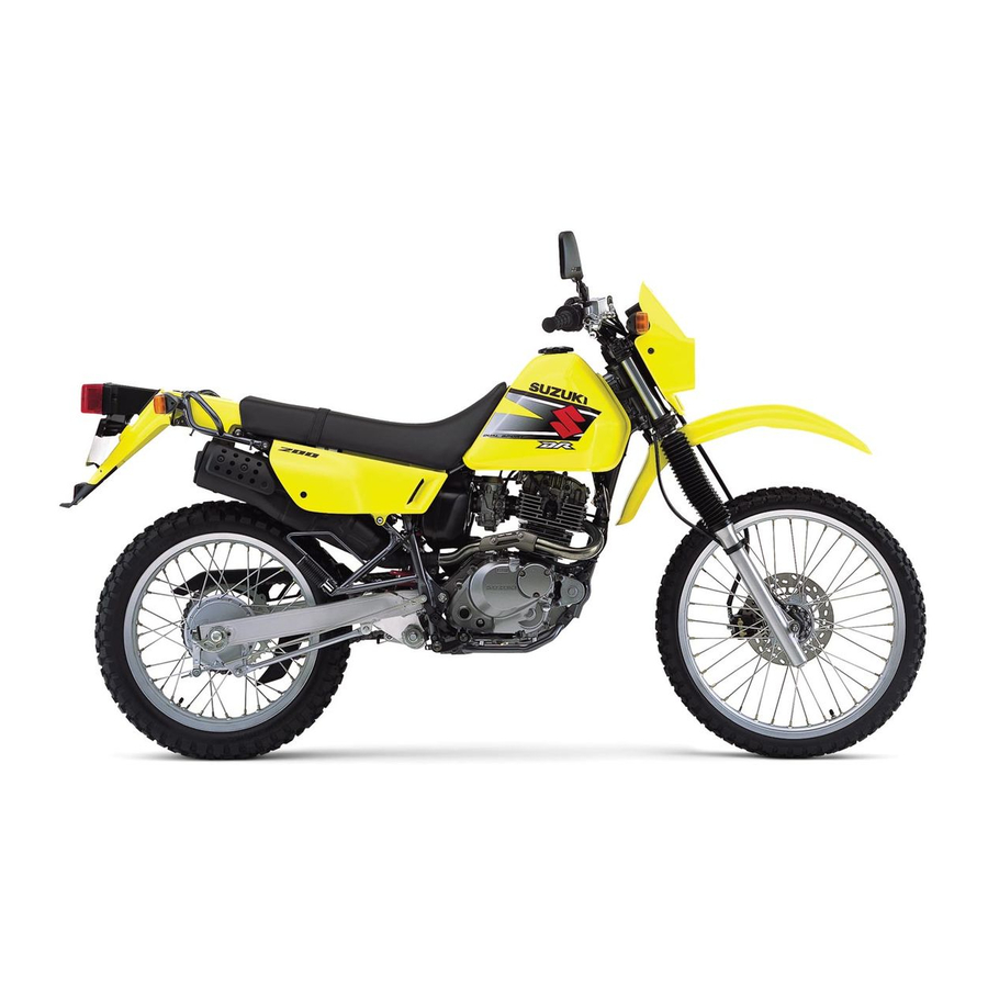
User Manuals: SUZUKI DR200SE Dual-Sport Motorcycle
Manuals and User Guides for SUZUKI DR200SE Dual-Sport Motorcycle. We have
1
SUZUKI DR200SE Dual-Sport Motorcycle manual available for free PDF download: Service Manual
SUZUKI DR200SE Service Manual (263 pages)
SUZUKI DR200SE
Brand:
SUZUKI
| Category:
Motorcycle
| Size: 24.18 MB
Table of Contents
Electrical System
1
General Information
1
Group Index
1
Periodic Maintenance
1
Servicing Information
1
Supplements
3
Component Parts and Work to be Done
4
How to Use the Manual
4
Symbol
5
General Information
7
General Precautions
8
Fuel and Oil Recommendations
10
Serial Number Location
10
Vehicle View (Suzuki DR200SET) ('96-Model)
10
Break-In Procedures
11
Information Labels
12
Specifications
14
Country or Area (Symbols)
16
Periodic Maintenance
17
Periodic Maintenance Schedule
18
Lubrication Points
19
Air Cleaner
20
Exhaust Pipe Nuts
20
Maintenance and Tune-Up Procedures
20
Valve Clearance
21
Carbon Deposit
22
Fuel Line (Evap Hose - California Model Only)
22
Spark Arrester
22
Spark Plug
22
Carburetor Maintenance
23
Clutch Maintenance
23
Idle RPM (Idling Adjustment)
23
Throttle Cable Play
23
Engine Oil and Oil Filter
24
Drive Chain Adjustment
25
Drive Chain Checking
25
Drive Chain Maintenance
25
Brake Fluid Level
26
Drive Chain Cleaning and Lubricating
26
Brake Lever Play
27
Brake Pads
27
Brake Pedal Height and Free Travel
27
Air Bleeding the Brake Fluid Circuit
28
Brake Light Switch
28
Brake Shoe Wear
28
Tire Pressure
29
Tire Tread Condition
29
Tires Maintenance
29
Front Fork
30
Rear Suspension
30
Steering
30
Chassis Bolts and Nuts
31
Compression Pressure Check
33
Compression Test Procedure
33
High Oil Pressure
34
Low Oil Pressure
34
Oil Pressure Check
34
Oil Pressure Test Procedure
34
Engine
35
Engine Components Removable with the Engine in Place
36
Engine Removal
37
Engine Reinstallation
40
Exhaust Gas Sealer View
42
Tightening Torque
42
Cylinder Head
43
Engine Disassembly
43
Cylinder
44
Generator and Starter Gears
45
Piston
45
Clutch Cover
46
Neutral Switch
46
Oil Sump Filter
46
Clutch
47
Clutch Release Camshaft
48
Gearshift
48
Oil Pump
48
Crankcase
49
Primary Drive Gear
49
Gearshift Cam
50
Transmission
50
Crankcase Bearing/Oil Seal
51
Crankshaft
51
Cylinder Head Cover Distortion
52
Cylinder Head Cover Service
52
Engine Components Inspection and Service
52
Rocker Arm I.D.
52
Cylinder Head Service
53
Rocker Arm and Shaft Reassembly
53
Cylinder Head Distortion
54
Valve Face Wear
54
Valve Stem Runout
54
Valve Guide Service
55
Valve Head Radial Runout
55
Valve Stem Deflection
55
Valve Stem Wear
55
Valve Seat Service
57
Valve Seat Width
57
Valve Stem End Condition
58
Valve and Valve Spring Reassembly
59
Valve Spring
59
Camshaft Cam Wear
60
Camshaft Journal Wear
60
Camshaft Runout
61
Cylinder Bore
61
Cylinder Distortion
61
Piston Diameter
61
Piston Ring Free End Gap and Piston Ring End Gap
62
Piston Ring-Groove Clearance
62
Conrod Small End I.D.
63
Oversize Rings
63
Piston Pin and Pin Bore
63
Conrod Deflection and Conrod Big End Side Clearance
64
Crankcase Runout
64
Oil Filter Removal
64
Clutch Drive Plate
65
Clutch Driven Plate
65
Clutch Release Bearing
65
Clutch Spring Free Length
65
Starter Clutch
66
Starter Clutch Disassembly
66
Starter Clutch Reassembly
66
Starter Driven Gear Bearing
66
Transmission Disassembly
67
Transmission Gears Diagram
67
Countershaft and Driveshaft Reassembly
68
Crankcase Bearing
70
Shift Fork-Groove Clearance
70
Engine Reassembly
71
Oil Seal
71
Crankshaft Diagram
72
Gearshift Mechanism
73
Crankcase Reassembly
75
Clutch Release Camshaft Installation
77
Oil Pump Mounting
77
Clutch Diagram
78
Clutch Release Screw Adjustment
80
Cam Drive Chain, Starter Gears and Generator
81
Oil Ring
82
Top Ring and 2Nd Ring
83
Cylinder Head Installation
84
Cylinder Mounting
84
Camshaft
85
Cylinder Head Cover
86
Cam Drive Chain Tension Adjuster
87
Cam Timing Inspection Cap and Generator Cover Cap
87
Valve Inspection Cap and Spark Plug
87
Fuel and Lubrication System
89
Fuel Filter Cleaning
90
Fuel Tank and Fuel Valve
90
Fuel Tank Removal
90
Fuel Valve Removal
90
Carburetor Exploded View
91
Carburetor Disassembly
92
Carburetor ID Number
92
Carburetor Specifications
92
Carburetor Cleaning
94
Pilot Screw Removal
95
Carburetor Jet Inspection
96
Float Height Adjustment
96
Needle Valve Inspection
96
Reassembly and Remounting
96
Engine Lubrication System Chart
97
Oil Sump Filter Cleaning
98
Chassis
99
Frame Cover and Seat Removal and Remounting
100
Fron Wheel Removal
101
Front Wheel Diagram
101
Front Axle Inspection
102
Spoke Nipple
102
Wheel Bearings Inspection
102
Wheel Rim Inspection
102
Front Wheel Reassembly and Remounting
103
Wheel Hub Bearing Installation
103
Brake Disc
104
Front Axle Nut
104
Speedometer Gearbox
104
Front Brake Diagram
106
Brake Fluid Replacement
107
Brake Pad Replacement
107
Caliper Removal and Disassembly
108
Caliper Inspection
109
Caliper Reassembly and Remounting
109
Disc Inspection
110
Disc Servicing
110
Master Cylinder Removal and Disassembly
111
Master Cylinder Inspection
112
Master Cylinder Reassembly and Remounting
112
Front Fork Diagram
114
Front Fork Removal and Disassembly
114
Fork Springs Inspection
116
Damper Rod Ring
117
Front Fork Reassembly and Remounting
117
Inner and Outer Tubes
117
Tube Metals and Seals
117
Damper Rod Bolt
118
Fork Oil
118
Fork Spring
118
Stopper Ring
118
Steering Diagram
120
Steering Removal and Disassembly
120
Steering Inspection
123
Steering Stem Nut
124
Steering Stem Reassembly and Remounting
124
Handlebars
125
Rear Wheel and Rear Brake Diagram
126
Rear Wheel and Rear Brake Removal
126
Brake Shoe
128
Rear Brake Drum
128
Rear Sprocket
128
Rear Wheel and Rear Brake Inspection and Disassembly
128
Rear Wheel Reassemby and Remounting
129
Rear Brake Installation
130
Rear Sprocket Installation
130
Rear Axle
131
Rear Suspension Diagram
132
Rear Suspension Removal
133
Cushion Lever Inspection
135
Swingarm Inspection
135
Shock Absorber Inspection
136
Swingarm Pivot Shaft Inspection
136
Rear Suspension Reassembly and Remounting
137
Swingarm Installation
137
Final Inspection and Adjustment
139
Shock Absorber Spring Pre-Load Adjustment
139
Shock Absorber Spring Setting Table
139
Electrical System
141
Caution on Clamp
142
Caution on Coupler
142
Caution on Fuse
142
Electrical System: Cautions in Servicing
142
Caution on Battery
143
Connecting Battery
143
Using Pocket Tester
143
Wiring Procedure
143
Location of Electrical Components
144
Charging System Description
145
Function of Regulator
145
Electrical System Troubleshooting
147
AC Generator No-Load Performance
148
Battery Leak Current Inspection
148
Charging Output Check
148
Generator Stator Coil
149
Regulator/Rectifier
149
Starter System Description
150
Starter System Troubleshooting
151
Carbon Brush Inspection
152
Starter Motor Inspection
152
Starter Motor Removal and Disassembly
152
Armature Coil Inspection
153
Commutator Inspection
153
O-Ring
153
Starter Motor Reassembly
153
Starter Motor Relay Inspection
154
Side-Stand/Ignition Interlock System Description
155
Diode
156
Interlock System Inspection
156
Neutral Switch Inspection
157
Side-Stand Switch Inspection
157
Side-Stand/Ignition Interlock Relay Inspection
157
Ignition System Description
158
Ignition System Troubleshooting
158
Ignition Coil Check with Electro Tester
159
Ignition Coil Check with Pocket Tester
159
Ignition System Inspection
159
Signal Generator Coil Check
159
Carbon Deposit Check
160
Electrode's Condition
160
Spark Plug Gap Check
160
Spark Plug Inspection
160
Ignition Unit Check with Digital Ignitor Checker
161
Speedometer and Indicator Light Inspection
163
Speedometer and Indicator Light Removal and Disassembly
163
Headlight Diagram
164
Lamps
164
Tail/Brake Light Diagram
164
Turn Signal Light Diagram
164
Switches
165
Side-Stand/Ignition Interlock Relay
166
Starter Motor Relay
166
Turn Signal Relay
166
Battery Specifications
167
Filling Electrolyte
167
Initial Charging
167
Battery Servicing
168
Recharging Operation
169
Servicing Information
171
Engine Troubleshooting
172
Carburetor Troubleshooting
174
Electrical Troubleshooting
175
Battery Troubleshooting
176
Chassis Troubleshooting
176
Brakes Troubleshooting
177
Wiring Diagram
178
Wire Routing
179
Wire, Cable and Hose Routing
179
Cable Routing
181
Carburetor and Air Cleaner Hose Routing
182
Front Brake Hose Routing
183
Heat Shield Adhering
184
Mud Flap, Fuel Tank Cushion and Side-Stand Spring Set-Up
184
Special Tool
185
Tightening Torque - Engine
188
Tightening Torque - Chassis
189
Tightening Torque Chart for Other Bolts and Nuts
190
Service Data - Valve + Guide
191
Service Data - Camshaft + Cylinder Head
192
Service Data - Cylinder + Piston + Piston Ring
192
Service Data - Clutch
193
Service Data - Conrod + Crankshaft
193
Service Data - Oil Pump
193
Service Data - Carburetor
194
Service Data - Transmission + Drive Chain
194
Service Data - Electrical
195
Service Data - Wattage
195
Service Data - Brake + Wheel
196
Service Data - Suspension
196
Service Data - Fuel + Oil
197
Tire Pressure Table
197
Emission Control Information
199
Emission Control Carburetor Components
200
Evaporative Emission Control System (California Model Only) Diagram
201
Canister Hose Routing (California Model Only) Diagram
202
DR200SEV/W/X/Y/K1/K2/K3 ('97, '98, '99, '00, '01, '02, '03-Models)
203
DR200SEV/W/X/Y/K1/K2/K3 ('97, '98, '99, '00, '01, '02, '03-Models) Specifications
204
DR200SEV/W/X/Y/K1/K2/K3 ('97, '98, '99, '00, '01, '02, '03-Models) Service Data
206
Table of Contents
213
DR200SEK4/K5 ('04, '05-Models)
213
For E-03, 28, 33
214
Specifications for E-03, 28, 33
214
For E-06, 24
215
For E-06, 24
216
Service Data - for E-03, 28, 33
216
Oil Pump
218
Dr200Sek4/K5 Carburetor
219
Dr200Sek4/K5 Transmisstion + Drive Chain
219
Service Data for E-06, 24
223
Dr200Sek4/K5 Tire Pressuer/Fuel + Oil
229
DR200SEK4/K5 ('04, '05-Models) Tightening Torques
230
Generator Rotor Nut Reassembly
231
DR200SEK6 (’06-Model)
233
DR200SEK6 (’06-Model) Specifications
234
DR200SEK6 (’06-Model) Service Data
236
Brake Light/Taillight
247
Fuse
247
Headlight
247
High Beam Indicator Light
247
Neutral Indicator Light
247
Speedometer Light
247
Turn Signal Indicator Light
247
Turn Signal Light
247
Engine Oil Change
249
Fuel Tank, Including Reserve
249
L (3.4/2.9 Us/Imp Gal)
249
DR200SEK7/K8 ('07 & ’08-Models)
251
DR200SEK7/K8 ('07 & ’08-Models) Specifications
252
DR200SEK7/K8 ('07 & ’08-Models) Service Data
253
Dr200Sek7/K8 Suspension
259
Dr200Sek7/K8 Tire Pressuer Fuel + Oil
259
DR200SEK9 (’09-Model)
261
DR200SEK9 (’09-Model) Specifications
262
Advertisement
Advertisement
Related Products
Suzuki DR200SEV 1997
Suzuki DR200SEV 1998
Suzuki DR200SEV 1999
Suzuki DR200SEV 2000
Suzuki DR200SEV 2001
Suzuki DR200SEV 2002
Suzuki DR200SEV 2003
Suzuki DR200S
Suzuki DR200W 1998
Suzuki DR200W 1999
SUZUKI Categories
Motorcycle
Automobile
Motorcycle Accessories
Musical Instrument
Offroad Vehicle
More SUZUKI Manuals
Login
Sign In
OR
Sign in with Facebook
Sign in with Google
Upload manual
Upload from disk
Upload from URL