Sign In
Upload
Manuals
Brands
Suzuki Manuals
Outboard Motor
DF300
Suzuki DF300 Manuals
Manuals and User Guides for Suzuki DF300. We have
1
Suzuki DF300 manual available for free PDF download: Service Manual
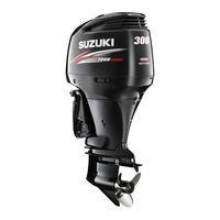
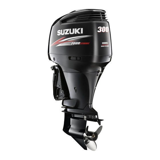
Suzuki DF300 Service Manual (593 pages)
Brand:
Suzuki
| Category:
Outboard Motor
| Size: 59.07 MB
Table of Contents
General Information 1
6
Table of Contents
6
Warning/Caution/Note
7
General Precautions
7
Identification Number Location
9
Fuel and Oil
10
Gasoline Recommendation
10
Engine Oil
10
Engine Break-In
11
Warm-Up Recommendation
11
Throttle Recommendation
11
Propellers
12
Powerhead Direction of Rotation
13
Suzuki Precision Control System
13
Cylinder Number
13
Specifications
14
Service Data
17
Tightening Torque
24
Special Tools
26
Materials Required
30
Periodic Maintenance
31
Periodic Maintenance Schedule
32
Periodic Maintenance Chart
32
Maintenance and Tune-Up Procedures
33
Engine Oil/Engine Oil Filter
33
Gear Oil
36
Lubrication
37
Spark Plug
38
Tappet Clearance
39
Idle Speed
46
Ignition Timing
47
Fuel Line
48
Low Pressure Fuel Filter
49
High Pressure Fuel Filter
49
Pcv System
50
Low Pressure Fuel Pump Filter
51
Water Pump/Water Pump Impeller
51
Propeller/Nut/Cotter Pin
51
Anodes
52
Bonding Wires
53
Battery
54
Bolts and Nuts
55
Oil Pressure
56
Cylinder Compression
58
Engine Control System
60
Engine Control System Structure
61
Components for System Control
63
Engine Control Module (Ecm)
63
Boat Control Module (Bcm)
64
Ecm Connector/Terminals Layout
66
Bcm Connector/Terminals Layout
67
Ecm and Bcm Internal Structure [Whole Structure]
68
Location of Sensor and Switch
71
Sensor and Switch
73
Switch Panel
80
Ignition System
84
Ignition Control System
85
Specifications
85
Electronic Fuel Injection System
87
Fuel Injection Control System
87
Fuel Delivery System Components
89
High Pressure Fuel Pump Control System
92
Low Pressure Fuel Pump Control System
93
Evaporation Purge System
93
Air Intake Components
94
Electronic Throttle System
95
VVT (Variable Valve Timing) SYSTEM
98
Electronic Shift System
100
Outline
100
Operation
100
Tachometer Monitor
101
Digital Display Screen
101
Caution System
102
Over-Revolution Caution System
103
Low Oil Pressure Caution System
103
Overheat Caution
104
Low Battery Voltage Caution System
105
Check Control Unit Communication Caution
105
Check Second Station Caution
106
Check Throttle System Caution
106
Check Shift Control Caution
107
Self-Diagnostic System
108
Code for Self-Diagnostic System Operation
108
Condition for Self-Diagnostic System Operation
110
Fail-Safe System
112
Pre-Programmed Value for Fail-Safe System
112
Oil Change Reminder System
114
Start-In-Gear Protection System
115
Inspection
116
Precaution on System Inspection
116
26-Pin & 34-Pin Test Cord
117
Inspection for Ecm Circuit Voltage
118
Inspection for Bcm Circuit Voltage
122
Inspection for Resistance
125
Component Inspections
126
Switch Panel
148
Removal/Installation
151
Flywheel
151
Ckp Sensor
153
Cmp Sensor
154
Oil Pressure Switch
154
OCV (Oil Control Valve)
155
Electronic Throttle Body Assembly
156
Clutch Link Rod
158
Troubleshooting
159
Engine Electrical
172
Battery Charging System
173
Outline
173
Inspection
175
Removal/Installation
181
Electric Starter System
183
Outline
183
Troubleshooting
185
Inspection
186
Starter Motor
189
Electric Parts Holder
201
Removal
201
Installation
203
Fuel System
204
Precautions When Servicing Fuel System
205
General Precaution
205
Fuel Pressure Relief Procedure
206
Fuel Line
207
Removal/Installation
207
Fuel Leakage Check Procedure
207
Fuel Hose Connection
208
Fuel Pressure Inspection
208
Low Pressure Fuel Pump/Fuel Vapor Separator Set
210
Removal
210
Fuel System Diagram
212
Inspection
213
Installation
213
Fuel Vapor Separator/High Pressure Fuel Pump
214
Removal and Disassembly
214
Inspection
216
Assembly
218
Evaporation Purge System
220
System Inspection
220
Purge Valve
220
Fuel Injector
222
Inspection
222
Removal
223
Installation
224
Low Pressure Fuel Pump
226
Inspection
226
Low Pressure Fuel Filter/Fuel Hose
227
Inspection
227
Power Unit
228
Ring Gear Cover and Air Intake Silencer Case
229
Removal
229
Installation
229
Cylinder Head Cover
230
Removal
230
Installation
232
Intake Collector Assembly
234
Removal
234
Installation
236
Power Unit
238
Removal
238
Installation
244
Oil Pump
249
Removal
249
Disassembly
250
Inspection
251
Measuring Pump Components
251
Assembly
252
Installation
253
Timing Chain
254
Removal
254
Inspection
258
Installation
260
Cylinder Head Assembly
267
Removal
267
Assembly
269
Disassembly
274
Inspection/Servicing
275
Reassembly
285
Cylinder/Crankshaft/Piston
287
Disassembly
287
Inspection/Servicing
290
Reassembly
302
Thermostat
309
Removal
309
Inspection
309
Installation
310
Operation
311
Engine Lubrication System
311
Water Cooling System
313
Pcv System
314
MID Unit
315
Engine Side Cover
316
Removal
316
Installation
316
Driveshaft Housing and Oil Pan
317
Removal
317
Inspection
323
Assembly
326
Swivel Bracket, Steering Bracket and Clamp Bracket
333
Removal
333
Inspection
336
Reassembly
337
Water Pressure Valve
342
Removal
342
Inspection
342
Installation
342
Power Trim and Tilt
343
System Wiring Diagram
344
Service Procedure
345
Oil Level
345
Air Bleeding
345
Power Trim and Tilt Unit
346
Removal
346
Disassembly
348
Cleaning and Inspecting
351
Reassembly
353
Ptt Motor
357
Removal
357
Disassembly
357
Inspection
358
Assembly
359
Installation
361
Ptt Motor Relay
363
Ptt Switch
364
Tilt Limit Switch
364
Operation
365
Component Parts
365
Principles of Operation
365
Lower Unit [Standard Rotation (Right-Hand) Model]
372
Removal & Disassembly
373
Inspection
380
Propeller
380
Gearcase
380
Gears/Bearing
380
Propeller Shaft Components
381
Propeller Shaft Bearing Housing
381
Shift Rod Guide Housing Components
382
Water Pump and Related Items
383
Driveshaft Oil Seal Housing
383
Driveshaft
384
Assembly & Installation
385
Trim Tab
397
Lower Unit Gears- Shimming and Adjustment
398
Lower Unit [Counter Rotation (Left-Hand) Model]
405
Removal & Disassembly
406
Inspection
414
Propeller
414
Gearcase
414
Gears/Bearing
415
Forward Gear Bearing/Thrust Bearing
415
Propeller Shaft Components
415
Propeller Shaft Bearing Housing
416
Shift Rod Guide Housing Components
417
Water Pump and Related Items
417
Driveshaft Oil Seal Housing
418
Driveshaft
418
Assembly & Installation
419
Trim Tab
433
Lower Unit Gears- Shimming and Adjustment
434
Wire/Hose Routing
441
Wiring Diagram
442
Df300
442
For Single Engine
442
For Single Engine and Dual Station
444
For Multiple Engine
445
For Multiple Engine and Dual Station
446
Wiring
448
Single Engine, Single Station
448
Single Engine, Dual Stations
449
Twin Engines, Single Station
450
Twin Engines, Dual Stations
451
Triple Engines, Single Station
452
Triple Engines, Dual Stations
453
Wire Routing
454
Fuel/Water Hose Routing
460
Fuel Hose Routing
460
Water Hose Routing
464
Section 12
467
Specifications
471
Service Data
471
Engine Control
478
Ecm
478
Shift Learning
478
MID Unit
480
Shift Actuator Holder
480
Power Unit
481
Crankcase
481
Collector Cover
481
FUEL HOSE (Fuel Tank to Low Pressure Fuel Filter)
482
Water Hose
482
Lower Unit
483
Propeller Shaft/Forward Thrust Washer
483
Clutch Dog Shifter
483
Section 13
485
Service Data
489
Ecm
496
Ecm
496
Wiring Harness
496
Engine Control
496
Power Unit
499
Camshaft
499
Wiring Diagram
500
Section 14
504
Service Data
508
Engine Control
515
Ecm
515
Ckp Sensor
515
General Information
515
Identification Number Location
515
Power Unit
516
Piston
516
Power Trim and Tilt
517
Mooring
517
Lower Unit
518
Connector Pin
518
Wire Routing
519
(30002F-110001 -, 30002Z-110001 -) Foreword
521
Specifications
522
Service Data
525
Materials Required
532
Special Tools
532
Periodic Maintenance
533
Maintenance and Tune-Up Procedures
533
Engine Control System
535
Engine Control System Structure
535
Components for System Control
537
Ignition System
543
Electronic Fuel Injection System
544
Inch/2 Inch Gauge
546
Caution System
547
Water in Fuel Alart System
554
Oil Change Reminder System
555
Self-Diagnostic System
556
Fail-Safe System
561
Inspection
563
O 2 Sensor
569
Troubleshooting
570
Fuel System
571
Low Pressure Fuel Filter
571
Power Unit
572
Cylinder
572
Power Trim and Tilt
574
Setting of Trim down Position Limit
574
Wire/Hose Routing
576
Wiring Diagram
576
Wiring
582
Wire Routing
588
Advertisement
Advertisement
Related Products
Suzuki DF 30
Suzuki DF350A
Suzuki DF300B
Suzuki DF325A
Suzuki DF300BMD
Suzuki DF350AMD
Suzuki DF225
Suzuki DF 70
Suzuki DF4A
Suzuki DF50A
Suzuki Categories
Motorcycle
Automobile
Motorcycle Accessories
Musical Instrument
Offroad Vehicle
More Suzuki Manuals
Login
Sign In
OR
Sign in with Facebook
Sign in with Google
Upload manual
Upload from disk
Upload from URL