Sign In
Upload
Manuals
Brands
Stratus Manuals
Server
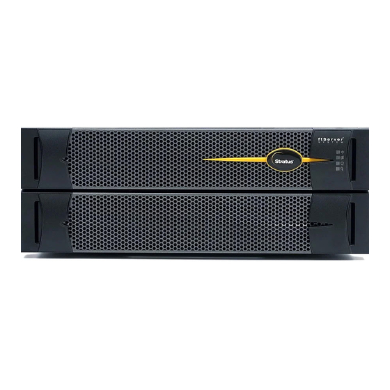
ftServer 2900 Series
Stratus ftServer 2900 Series Server Manuals
Manuals and User Guides for Stratus ftServer 2900 Series Server. We have
1
Stratus ftServer 2900 Series Server manual available for free PDF download: Planning And Installation Manual
Stratus ftServer 2900 Series Planning And Installation Manual (148 pages)
Brand:
Stratus
| Category:
Server
| Size: 1.94 MB
Table of Contents
Table of Contents
3
Preface
11
Site Planning for Ftserver 2900, 4900, and 6900 Systems
17
Site Planning Overview
17
The Stratus Activeservice Network
19
Site Planning Checklist
19
Table 1-1. Ethernet Pcie Adapters
20
Chapter 2
22
Redundant Power Sources
22
System Documentation
23
Table 1-2. Ftserver 2900, 4900, and 6900 System Documentation
23
Table 1-3. Additional System Documentation for Windows-Based Systems
24
Table 1-4. Additional System Documentation for Linux-Based Systems
25
Table 1-5. Additional System Documentation for Vmware Vsphere-Based Systems
25
Electrical Power Planning
27
Redundant Power Sources
27
AC Power and HVAC Service Requirements
28
Table 2-1. Worksheet: Determining A-Side Power Requirements
29
Table 2-2. Worksheet: Determining B-Side Power Requirements
29
Table 2-3. Worksheet: Determining External Power Requirements
29
AC Power Outlet Requirements
30
Table 2-4. HVAC Requirements
30
Table 2-5. Worksheet: A-Side External Power Outlet Requirements: Pdus Used
30
Table 2-6. Worksheet: B-Side External Power Outlet Requirements: Pdus Used
30
Connecting a System Directly to Separate AC Sources
31
Table 2-7. Worksheet: A-Side External Power Outlet Requirements: no Pdus
31
Table 2-8. Worksheet: B-Side External Power Outlet Requirements: no Pdus
31
Selecting a UPS Unit for Ftserver Systems
32
Communicating with a UPS over a Network
32
Connecting a System Directly to a UPS
33
Power Cord Summary
33
Power Cords for Ftserver Systems and Peripheral Components
33
Table 2-9. Power Cords - Ftserver Systems and Peripheral Components to AC Power
33
Table 2-10. Power Cords between Ftserver Systems or Storage Systems and a UPS
34
PDU Power Cords
35
Table 2-11. Power Cords to Connect Pdus Directly to AC Power Mains
35
Table 2-12. Power Cords to Connect Pdus to a UPS
35
Grounding Requirements
36
Table 2-13. System Power (Jumper) Cables to Connect Ftserver Systems to Pdus
36
Space Planning
37
Room Requirements
37
Planning for Cables
39
Communications Line Planning
41
Chapter 4
42
Supported Host Bus Adapters
42
Supported Storage Systems
42
Table 4-1. Hbas Supported by Ftserver 2900, 4900, and 6900 Systems
42
Table 4-2. Storage Systems Supported by Ftserver 2900, 4900, and 6900 Systems
42
Connections from Storage Systems to Ftserver Systems
43
Fibre Channel Connections
43
Table 4-3. Optical FC Cables
43
Iscsi Connections
44
Ethernet Cables
45
Table 4-4. Customer-Supplied Ethernet Cables
46
Category-6/Category-6A Cables
48
Telephone Line Connections
49
N O T E S
49
Rack Configuration Planning
51
Using Pdus
51
Determining PDU Requirements
52
Table 5-1. Current and Rack-Space Requirements
53
Example of PDU Usage Calculation
54
Table 5-2. Calculating A-Side PDU and Rack-Space Requirements
54
Table 5-3. Example: Current and Rack-Space Requirements (208 Volts)
54
Table 5-4. Example: Calculating A-Side PDU and Rack-Space Requirements
55
Cabinet and Monitor Requirements
57
Cabinet Requirements
57
Figure 6-1. Rail Clearance
60
Monitor Requirements
61
Site Planning for Peripheral Components
63
Ftscalable Storage System Requirements
63
Table 7-1. Site Planning for Ftscalable Storage G3 Systems
63
Chapter 7
64
Keyboard Requirements
64
Table 7-2. V115 Keyboard: Specifications
64
Peripheral Components for Windows-Based Systems
65
Table 7-3. PCI Adapters and Peripheral Components: Windows-Based Systems
65
Peripheral Components for Linux-Based Systems
66
Table 7-4. PCI Adapters and Peripheral Components: Linux-Based Systems
66
Peripheral Components for Vmware Vsphere-Based Systems
67
Table 7-5. PCI Adapters and Peripheral Components: Vmware Vsphere-Based Systems
67
Table
67
Before You Install the System
69
Safety Considerations
69
Safety Notices
69
Consignes de Sécurité
72
Installing the System in a Cabinet
79
Figure 9-1. System Components
80
Required Tools
81
Numbering the Vertical Rails
81
Figure 9-2. EIA Vertical Rail Hole Pattern
82
Figure 9-3. Numbering the Middle Hole of 6U
83
Installing Pdus (Optional)
84
PDU Components
84
Figure 9-4. PDU Components
85
Figure 9-5. Cage Nut Locations: PDU
86
Figure 9-6. Inserting Cage Nuts
87
Figure 9-7. Installing the Lower PDU (at U Number 1)
88
Installing a System Chassis
89
Figure 9-9. Screw Locations on the Rear Vertical Rails
90
Figure 9-10. Attaching the Mounting Brackets and Inserting Guide
91
Figure 9-11. Removing the Front Panel from the Shelf Unit
92
Figure 9-12. Removing the System Backplane
93
Figure 9-13. Cage Nut Locations on Front Vertical Rails
94
Figure 9-14. Mounting the Shelf Unit on the Mounting Brackets
95
Figure 9-15. Securing the Shelf Unit to the Front Rails
96
Figure 9-16. Securing the Shelf Unit to the Mounting Brackets
97
Figure 9-17. Replacing the Front Panel in the Shelf Unit
98
Installing the System Enclosures
99
Figure 9-18. Installing the CPU-I/O Enclosures in a Cabinet
100
Figure 9-19. Installing the Bezel
102
Next Steps
102
Connecting the System Components and Peripherals
103
Chapter 10
104
PCI Adapters
104
System Ports and Backplane
105
Figure 10-1. System Ports
105
Managing Cables
106
Connecting a Monitor, Mouse, and Keyboard
106
Connecting the Ftserver System to External Storage Systems
106
Connecting Ftserver Systems to the Network for Iscsi Access
107
Connecting the VTM Ports to a Network
109
Connecting the External Modem
109
Figure 10-2. Connecting Cables to the Modem
110
Connecting Tape Drives (Windows- and Linux-Based Systems)
111
Figure 10-3. Mini-SAS (SFF-8088) Connector
111
Next Steps
112
Figure 10-4. Connecting a Tape Drive to an Ftserver System
112
Connecting the System to Electrical Power
113
System Power Overview
113
Connecting the System to AC Power (Mains)
114
Connecting the System Directly to a UPS
115
Figure 11-1. Connecting a System Directly to AC Power
115
Figure 11-2. Connecting a System to a UPS
117
Connecting Systems to Power through Pdus
118
Figure 11-3. Connecting the Systems Directly to Pdus
119
Next Steps
120
Appendix A. System Specifications
121
System Specifications
121
Figure A-1. Ftserver 2900, 4900, or 6900 System: CPU-I/O Enclosures: Front View
122
Table A-1. Cabinet Dimensions
123
Table A-2. Ftserver 2900, 4900, 6900 System Unit Specifications
124
Pcie Adapter Specifications
126
Table A-3. Pcie Adapter Specifications
126
AAP87600 PDU Specifications
127
Figure A-2. AAP87600PDU
128
Table A-4. AAP87600 PDU: Specifications
129
Appendix B. Electrical Circuit and Wiring Information
131
Fault Protection Requirements
131
Grounding Considerations
131
Circuit Wiring Diagrams
132
Ftserver Enclosure Power Input Labeling
133
Figure B-4. Single-Phase 120V AC Circuit Connection
134
Figure B-5. Single-Phase 240V AC Circuit Connection
135
Figure B-6. Split-Phase 120/240 Volts AC Circuit Connection
136
Electrical Power Connectors
139
Table B-1. Connectors for AC Power Outlets
139
PDU Safety Considerations
140
Appendix C. Hardware Replacement and System Support
143
Index
145
Advertisement
Advertisement
Related Products
Stratus ftServer 2600
Stratus ftServer W 2300Series
Stratus ftServer 2510
Stratus ftServer 2500
Stratus ftServer W 2300 Series
Stratus ftServer 4900 Series
Stratus ftServer 6900 Series
Stratus ftServer 3000 Series
Stratus 2S
Stratus AA-E99100
Stratus Categories
Lifting Systems
Server
Scissor Lifts
Receiver
PCI Card
More Stratus Manuals
Login
Sign In
OR
Sign in with Facebook
Sign in with Google
Upload manual
Upload from disk
Upload from URL