Sign In
Upload
Manuals
Brands
Stratasys Manuals
3D Printers
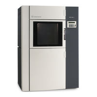
Fortus 400mc
Stratasys Fortus 400mc Manuals
Manuals and User Guides for Stratasys Fortus 400mc. We have
6
Stratasys Fortus 400mc manuals available for free PDF download: Service Manual, Manual, User Manual, Site Preparation Manual, Quick Reference Card
Stratasys Fortus 400mc Service Manual (444 pages)
3D Production System
Brand:
Stratasys
| Category:
3D Printers
| Size: 13.48 MB
Table of Contents
Table of Contents
3
Safety
13
Safe Environment
13
Safe Human Interface
13
Hazard Classifications
13
Potential Safety Hazard Areas
14
Guard Door Interlocks
15
Safety
17
Safe Environment
17
Safe Human Interface
17
Hazard Classifications
18
General Safety Practices
19
Potential Safety Hazard Areas
19
Guard Door Interlocks
19
Removing Electrical Power
20
Specifications
22
System Specifications
22
Liquefier Tip Specifications
24
Theory of Operation
32
General
32
FDM Technology
32
Extrusion
32
First Layer Adhesion
34
Thermal Expansion
36
Systems
37
AC Board
37
Computer
39
Z Stage
39
MIO Board
40
Head
42
Head Cooling Fan
45
Gantry (XY Table)
47
Canister
50
Canister Drive Block
52
Loading/Unloading Filament to the Head
56
Door Interlock
60
Air Dryer System
61
Operation
62
Vacuum System
63
Oven Temperature Control
66
Thermal Safety Circuit
68
Calibration and Sensors
70
Homing
70
Z Stage Homing
71
Gantry Homing
72
Auto Z Zero
73
Measure Flatness
74
Tip Sensor
74
Linear Compensation
76
General Information
78
Installation Checklist
78
Installation
78
Un-Crate the System
78
Stabilize System
78
Pre-Power up Checks
79
AC Power Verification
88
Initial Power Up, Network Configuration and System Activation
90
Upgrade Controller Software
96
System Verification and Calibration
97
Final Test
98
Software
100
Insight
101
Building a Part
101
Start Insight
101
Open an STL File
101
Modeler Set-Up
102
Prepare the Part
105
User Interface (UI) Menu Structure
110
Main Menu
110
Build Job
110
Show Job Queue
110
Show Sample Job Queue
110
Operator Control
110
Load/Unload Material
111
Calibrate
111
Temp Control
111
Move Head/Stage
111
Main Menu
111
Modeler Status
113
Temperatures
115
Material Status
115
Tip Status
115
Machine State
115
Main Menu
115
Maintenance
118
Modeler Default
118
Administration
118
Reboot Machine
118
Procedures
118
Main Menu
118
Procedures
123
Service Procedures
124
General
128
Panels
128
Panel Removal
129
Panel Installation
130
System Power Down/Power up
131
System Power down
131
System Power up
132
Operator Power Down/Power up
133
Operator Power down
133
Operator Power up
133
Oven Door Window
134
Oven Door Window Removal
134
Oven Door Window Installation
135
Head
136
Head Maintenance Position
136
Place Head in the Maintenance Position
136
Place Head in the Operating Position
137
Head Cable
138
Head Cable Removal
138
Head Cable Installation
139
Liquefier Tip
140
Liquefier Tip Removal
140
Liquefier Tip Installation
141
Head
142
Head Removal
142
Head Installation
143
XY Gantry
144
XY Gantry Cooling Fans
144
Gantry Cooling Fans Removal
144
Gantry Cooling Fans Installation
145
Y Carriage Kapton Barrier
146
Y Carriage Kapton Barrier Replacement
146
And y Belt
147
And y Belt Removal
147
And y Belt Installation
149
And y Pulley
151
And y Pulley Removal
151
And y Pulley Installation
152
And y Motor
154
And y Motor Removal
154
And y Motor Installation
155
And y Bellows
157
And y Bellows Removal
157
And y Bellow Installation
158
Y Bridge
159
Y Bridge Removal
159
Y Bridge Installation
163
X-Axis Guide Rod/Pillow Block
167
X-Axis Guide Rod/Pillow Block Bearing Removal
167
X-Axis Guide Rod/Pillow Block Bearing Installation
171
Z Stage
176
Z Drive Motor
176
Z Drive Motor Removal
176
Z Drive Motor Installation
178
Lead Screw Assembly
179
Z Lead Screw Removal
180
Z Lead Screw Installation
181
Z Guide Rod/Pillow Block
186
Z Guide Rod/Pillow Block Removal
187
Z Guide Rod/Pillow Block Installation
188
Z Stage Drive Belt
190
Z Stage Drive Belt Removal
190
Z Stage Drive Belt Installation
191
Z Stage Idler Pulley
192
Z Stage Idler Pulley Removal
192
Z Stage Idler Pulley Installation
193
Platen Vacuum Screen
194
Vacuum Screen Removal
194
Vacuum Screen Installation
194
Platen
195
Platen Removal
195
Platen Installation
196
Electronic Components
197
Display Panel
197
Display Panel Removal
197
Display Panel Installation
198
AC Board
198
AC Board Removal
198
AC Board Installation
200
MIO Board
201
MIO Board Removal
201
MIO Board Installation
202
24/48 Volt Power Supply
204
24/48 Volt Power Supply Removal
204
24/48 Volt Power Supply Installation
205
Ups
207
UPS Removal
207
UPS Installation
207
Computer
208
Computer Removal
208
Computer Installation
209
Oven Components
210
Upper Waste Chute Funnel Kapton Barrier
210
Upper Waste Chute Funnel Kapton Barrier Replacement
210
Oven Blower
211
Oven Blower Removal
211
Oven Blower Installation
214
Oven Thermocouple
216
Oven Thermocouple Removal
216
Oven Thermocouple Installation
217
Oven Thermal Circuit Breaker
219
Oven Thermal Circuit Breaker Removal
219
Oven Thermal Circuit Breaker Installation
220
Oven Heaters
221
Oven Heaters Removal
221
Oven Heaters Installation
226
Oven Blanket (Right Side)
227
Oven Blanket (Right Side) Removal
227
Oven Blanket (Right Side) Installation
230
Oven Blanket (Left Side)
230
Oven Blanket (Left Side) Removal
230
Oven Blanket (Left Side) Installation
231
Tip Sensor/Tip Sensor Cable
232
Tip Sensor/Cable Removal
232
Tip Sensor/Cable Installation
233
Filament Path
235
Filament Drive
235
Filament Drive Removal
235
Filament Drive Installation
237
Y Block
239
Y Block Removal
239
Y Bock Installation
240
Internal Air Components
241
Internal Vacuum Pump
241
Internal Vacuum Pump Removal
241
Internal Vacuum Pump Installation
242
Internal Air Compressor
243
Internal Air Compressor Removal
243
Internal Air Compressor Installation
244
Calibrations
245
Autohome XYZ
246
Calibrations
246
Z Zero Calibrations
247
Manual Z Zero Calibration
247
Auto Z Zero Calibration
248
Tip Offset Calibrations
249
Autocal Tips
249
XYZ Tip Offset
250
Ppu/Scaling Calibration
254
Adjustment
256
Platen Level Adjustment
256
Upper Z Stage Hard Stop Adjustment
260
Head Filament Alignment
263
Head Filament Presence Detect Switch Adjustment
265
Belt Tension Gauge Setup
267
XY Gantry Belt Tension
268
Z Stage Belt Tension
272
Tip Wipe Height Adjustment
274
Standard Tip Wipe Assembly
274
Quick Adjust Tip Wipe Assembly
277
Air Pressure and Air Flow Adjustment
278
Z Homing Switch Adjustment
279
Tip Air Deflector Adjustment
281
Interlock Switch and Sensor Adjustments
282
Tip Sensor Location/Setting Position
283
Purge Location/Setting Position
284
Troubleshooting
285
How to Use this Guide
286
General Information
286
Who Should Use this Guide
286
Systems Covered by this Guide
286
Alternate Troubleshooting References
286
How to Troubleshoot the System
286
Definition of Terms
287
System Problems
288
Power
288
System will Not Power up
288
System will Not Power down
289
System Powers down Unexpectedly
290
Computer
291
User Interface Is Blank
291
User Interface Is Unresponsive (System Locked Up)
291
Computer Unable to Restart Properly
291
Vacuum
292
Calibration
292
Autohome XYZ Failed
292
Autocal Tip Failed
293
Build Failures
296
Part Build Won't Start
296
Part Build Stopped
299
Operation: Failure
300
Part Quality
301
Operation: Failure
306
Part Download Failed
306
Material Load Failed
307
Loss of Extrusion (LOE)
310
Operation: Condition
313
Odor/Burning
313
Error Messages
314
UI Messages
314
UI HELP Messages
315
CFG File ERROR Messages
316
Preventive Maintenance
317
PM Procedure Checklist
318
Preventive Maintenance Procedures
318
Lubricate the X y Gantry Guide Rods
318
Lubricate Z Stage
319
Head Cable Inspection
321
Filament Drive Inspection
323
Filament Drive Load Time Test
324
Internal Air Compressor Filters
325
Internal Vacuum Pump Filters Replacement
326
Cleaning Oven Door Glass
328
Drive Belt Inspection
328
Platen Inspection
328
Schematics
329
Cable Wiring Diagrams
332
Left/Right Fan Bay Cables 101266
332
Light Blower Cable 101325
333
RS485 Cable PIC Bus 101342
334
Oven Heater Cable 101428
335
Cassette Interface Cable 101470 Sheet 1 of 2
336
Z Limit Switch Cable 101471
338
Cassette LED Cable 101472
339
Display Internal Cable 101473
340
Display Switch Interface Cable 101474
341
RJ45 Communication Cable 101515
342
Door Switch Solenoid Cable 101543
343
Display Interface Cable 101786
344
Motor Cable 102349
345
Y Motor Cable 102350
346
Z Motor Cable 102351
347
Head Umbilical Cable 102628
348
Signal Motor Driver Board Cable 102630
349
Power Motor Drive Board Cable 102631
350
Filament Sensor Cable 102997
351
MIO AC Board Interface Cable 103027
352
Top Hood Switch Solenoid Cable 103029
353
Thermal Fuse Cable 103031
354
Twin Tower Tip Wipe Comp Cable 103033
355
Computer UPS Power Cable 103046
356
PCI Communication Cable 103047
357
24/48V to IO Cable 103049
358
Power Switch/Ups Vacuum Pump Cable 103050
359
24/48V Power Supply Cable 103054
360
Contactor Control Cable 103610-0002
361
Door/Hood Vane Switch 104466
362
Door Cover Solenoid 105569
363
Bay Communication Jumper 105570
364
Vacuum Switch 105571
365
Door Switch 105572
366
External Air Diagram
367
Specifications
371
System Specifications
371
Liquefier Tip Specifications
372
General Information
372
Tip Compatibility and Selection
372
Tip Identification and Slice Height
376
Material Build Temperatures
377
Removal and Replacement
378
Oven Door Window
378
Oven Door Window Removal
378
Oven Door Window Installation
381
Y Bridge
383
Y Bridge Removal
383
Y Bridge
384
Y Bridge Installation
384
X-Axis Guide Rod / Pillow Block
387
X-Axis Guide Rod / Pillow Block Removal
387
X-Axis Guide Rod / Pillow Block
388
X-Axis Guide Rod / Pillow Block Installation
388
Y-Axis Guide Rod Assembly
390
Y-Axis Guide Rod Assembly Removal
390
Y-Axis Guide Rod Installation
393
Electronic Components
395
Display Panel
395
Display Panel Removal
395
Display Panel Installation
397
Computer
398
Computer Removal
398
Computer Installation
399
Calibration and Adjustment
401
Linear Compensation
401
And y Belt Tension Settings
404
Component Adjustment
405
Tip Wipe Height Adjustment
405
Tip Clean Position / Purge Location
409
Filament Dryer Air Pressure and Air Flow
412
Interlock Switch and Sensor Adjustments
414
XY Gantry Ppu/Scaling Calibration (Alternate Method)
419
Advertisement
Stratasys Fortus 400mc Manual (162 pages)
Brand:
Stratasys
| Category:
3D Printers
| Size: 8.02 MB
Table of Contents
Table of Contents
7
Service and Support
13
360Mc/400Mc Service
13
Software Support
13
Safety Instructions
14
Hazard Types
14
Product Safety Signs
15
Specific Safety Practices
16
Guard Door Interlocks
16
General Safety Practices
17
Setup and Installation
19
General Information
19
Prepare Your Facility for Installation
19
Identifying Your System
19
Basic Setup
19
Making the Network Connection
19
Making the External Air Connection
20
Making the Power Cable Connection
20
Network Setup
21
Configuring the Network
21
Setting the IP Address
21
Moving the System
23
System Components
27
System Protection
27
Main Circuit Breaker
27
Thermal Cut-Out Fuses
27
Ups
27
Access Doors and Panels
28
Top Door and Top Hood
29
Oven Door
29
Canister Bay Doors
29
Right Side Door - Upper
29
Right Side Door - Lower
29
Left Side Door - Upper
30
Left Side Door - Lower
30
Gantry Area (XY Table)
30
Opening the Top Door and Top Hood
30
XY Gantry Assembly
30
Head Assembly
31
Head Maintenance Bracket
32
Modeling Materials and Tips
33
Materials
33
Liquefier Tips
34
Oven Bay
37
Oven Door
37
Oven Components
38
Canister Bay
41
Accessing the Bays
41
Canister Bay Components
41
Smartspool System
43
Vacuum and Air Dryer Systems
45
On Board Vacuum System
45
On Board Air Dryer System
45
Operating the System
47
Basic User Interface and Operations
47
Using the Keypad
48
Screen Symbols
49
Powering up the System
49
Powering down the System
50
Basic Job Build Tasks
51
Before a Job Build
51
Select a Job to Build
53
Build Job Warnings
54
Information Available During a Build
55
Pausing or Aborting a Job
56
After a Job Build
57
Removing Supports
58
Breakaway Support Material
58
Soluble Release Support Material
58
Support Material for PPSF Parts
58
Material, Canisters, and Liquefier Tips
58
Unloading Material from the Liquefier Tips
58
Removing Canisters
59
Canister Installation
61
Loading Material to the Liquefier Tips
64
Canister Auto Change-Over
65
Handling/Storing Canisters
66
Changing Tips or Material Type
67
Working with the Job Queues
75
Change Modeler Default Values
76
Display Units
76
Part Build Location
76
System Status
78
Temperature Status
78
Odometer Status
78
Material Status
79
System Software Version
80
Sensor, System, or UPS Status
80
Miscellaneous Operating Tasks
81
Oven Temperature Control
81
Operator Control of Head and Z Stage Movement
82
Operating Insight
85
Getting Started with Insight
85
Starting Insight
85
Opening an STL File
85
Modeler Setup - Insight
86
Configure Your Modeler
86
Part Build Parameters
87
Preparing the Model - Insight
88
Orienting the Part in the Build Envelope
88
Slicing the Part
89
Building Supports and a Base for the Part
89
Saving the Job File
89
Creating Toolpaths
89
Saving the Toolpath (CMB File)
90
Flag Button Shortcut
90
Sending a Part to the Modeler
91
Calibration
93
Automatic Calibration
93
Auto Z Stage Zero Calibration
93
Auto Tip-To-Tip Calibration (Autocal Tip Offset)
94
XY and Z Tip Offset Calibration
94
Manual Calibration
98
Manual Z Stage Zero
98
Auto Z Stage Zero Calibration - Manual Start
100
Auto Tip-Tip Calibration (Autocal Tip Offset) - Manual Start
101
XY and Z Tip Offset - Manual Start
102
System Maintenance
103
Updating Controller Software
103
Web Method (Preferred Method)
103
CD Method (Alternate Method)
104
Placing System in Receive Software Upgrade Mode
104
Maintenance Schedule
105
Daily Maintenance
106
Clean the Platen
106
Empty the Purge Waste Bucket
106
Weekly Maintenance
107
Vacuum the Build Envelope
107
Clean/Inspect Tip Wipe Assembly
107
Quarterly Maintenance
110
Inspect the Platen O-Ring
110
Clean the Vacuum System In-Line Filter and Jar
110
Clean the Tip Sensor Plunger
111
As Needed Maintenance
112
Upgrading Software or Entering a System Code
112
Platen Flatness Diagnostic
113
Clean Exterior Surface of System
114
Clean the Liquefier Tips
114
Replace an Interior Lamp
114
Troubleshooting
115
Getting Help
115
Finding a Remedy
116
PPSF Materials User Guide
121
Introduction to PPSF
121
Terminology
121
Hazard Classifications
122
Pre-Processing
122
Setting up PPSF in Insight (Version 6.0 or Later
122
Modeler Operation with PPSF
123
Switching to PPSF from Another Material
123
Replacing the Tip
123
Replacing the Purge Ledge
123
General Operation with PPSF
124
Removing PPSF_S Supports
124
Using the Support Removal Toolkit Items
126
Tool Maintenance
126
Support Removal Tool Kit
127
Reheating a PPSF Part
130
Reheating with the Modeler Oven
130
Reheating with a Convection or Consumer Oven
130
Reheating with Laboratory Ovens
131
Reheating with a Hot Air Gun
131
Material Safety Data Sheets (MSDS
131
Material Abbreviations
131
Finishing
131
Sealing/Adhesive
131
Sealing/Adhesive Data
132
Drilling and Sanding
132
UI Menu Structure
133
Main Menu
133
Waterworks
145
About Waterworks Soluble Concentrate
145
Service and Support
145
System, Material, and Liquefier Tip Compatibility
146
Abs (P400
146
Abs-Esd7
146
ABS-M30 (P430), ABS-M30I
146
Absi (P500
147
Pc-Abs
148
Tip Identification
149
Vantage and Titan System Tip Identification
149
Fortus System Tip Identification
149
Choosing a Support Removal Tank
150
Circulation Tanks
150
Ultrasonic Tanks
150
Safety Guidelines
151
Support Removal Items
151
Removing Support Material
152
Manually Removing Support Material
152
Removing SR-100 Support Material
152
Adding Solution to the Tank
152
Tank Temperature
153
Placing Parts in the Tank
153
Inspecting Parts and Solution
154
Removing Parts from the Tank
155
Changing Solution in the Tank
156
Disposing of Soluble Concentrate
157
Soluble Solution Drain Effluent
157
Neutralization
157
Support Removal Quick Reference
159
Minimize Cleaning Time in Support Removal Tank Solution
159
Sustain Proper Temperature of Support Removal Tank Solution
159
Stratasys Fortus 400mc User Manual (124 pages)
Brand:
Stratasys
| Category:
3D Printers
| Size: 2.18 MB
Table of Contents
Table of Contents
6
Chapter 1: Service and Support
10
Service
10
Software Support
10
Safety Instructions
11
Hazard Types
11
Product Safety Signs
12
Specific Safety Practices
13
Guard Door Interlocks
14
General Safety Practices
14
Chapter 2: Setup and Installation
15
General Information
15
Prepare Your Facility for Installation
15
Identifying Your System
15
Basic Setup
16
Making the Network Connection
16
Making the External Air Connection
16
Making the Power Cable Connection
16
Network Setup
17
Configuring the Network
17
Setting the IP Address
18
Moving the System
19
Chapter 3: System Components
22
System Protection
22
Main Circuit Breaker
22
Thermal Cut-Out Fuses
22
Ups
22
If Power Is Lost to the Modeler
23
During Normal System Power-Down
23
Access Doors and Panels
23
Top Door and Top Hood
24
Oven Door
24
Canister Bay Doors
24
Right Side Door - Upper
25
Right Side Door - Lower
25
Left Side Door - Upper
25
Left Side Door - Lower
25
Gantry Area (XY Table)
26
Opening the Top Door and Top Hood
26
XY Gantry Assembly
26
Head Assembly
27
Head Maintenance Bracket
27
Modeling Materials and Tips
29
Materials
29
Materials Used
29
Materials Compatibility
29
Liquefier Tips
30
Liquefier Tips and Slice Heights
30
Tip Compatibility & Selection
30
Tip Identification
33
Oven Bay
34
Oven Door
34
Oven Components
34
Oven Lamps
34
The Platen
35
Tip Cleaning Assembly
35
Z Stage
36
Canister Bay
37
Accessing the Bays
37
Canister Bay Components
37
Smartspool System
39
Vacuum and Air Dryer Systems
41
On Board Vacuum System
41
On Board Air Dryer System
41
Chapter 4: Operating the System
42
Basic User Interface and Operations
42
Using the Keypad
43
Screen Symbols
44
Powering up the System
44
Powering down the System
45
Basic Job Build Tasks
45
Before a Job Build
45
Select a Job to Build
47
Build Job Warnings
48
Information Available During a Build
50
Pausing or Aborting a Job
50
After a Job Build
51
Removing Supports
52
Breakaway Support Material
52
Soluble Release Support Material
52
Support Material for PPSF Parts
52
Material, Canisters, and Liquefier Tips
54
Unloading Material from the Liquefier Tips
54
Removing Canisters
55
Canister Installation
56
Loading Material to the Liquefier Tips
59
Canister Auto Change-Over
61
Handling/Storing Canisters
62
Changing Tips or Material Type
63
Working with the Job Queues
70
Change Modeler Default Values
71
Display Units
71
Part Build Location
72
System Status
73
Temperature Status
73
Odometer Status
73
Material Status
74
System Software Version
75
Sensor, System, or UPS Status
75
Miscellaneous Operating Tasks
76
Oven Temperature Control
76
Operator Control of Head and Z Stage Movement
77
Chapter 5: Operating Insight
80
Getting Started with Insight
80
Starting Insight
80
Opening an STL File
80
Modeler Setup - Insight
81
Configure Your Modeler
81
Part Build Parameters
82
Preparing the Model - Insight
83
Orienting the Part in the Build Envelope
83
Slicing the Part
84
Building Supports and a Base for the Part
84
Saving the Job File
84
Creating Toolpaths
84
Saving the Toolpath (CMB File)
85
Flag Button Shortcut
85
Sending a Part to the Modeler
86
Chapter 6: Calibration
87
Automatic Calibration
87
Auto Z Stage Zero Calibration
87
Auto Tip-To-Tip Calibration (Autocal Tip Offset)
88
XY and Z Tip Offset Calibration
88
Manual Calibration
92
Manual Z Stage Zero
92
Auto Z Stage Zero Calibration - Manual Start
94
Auto Tip-Tip Calibration (Autocal Tip Offset) - Manual Start
95
XY and Z Tip Offset - Manual Start
96
Chapter 7: System Maintenance
97
Updating Controller Software
97
Web Method (Preferred Method)
97
CD Method (Alternate Method)
98
Placing System in Receive Software Upgrade Mode
99
Maintenance Schedule
99
Daily Maintenance
100
Clean the Platen
100
Empty the Purge Waste Bucket
100
Weekly Maintenance
101
Vacuum the Build Envelope
101
Clean/Inspect Tip Wipe Assembly
101
Quarterly Maintenance
104
Inspect the Platen O-Ring
104
Clean the Vacuum System In-Line Filter and Jar
104
Clean the Tip Sensor Plunger
105
As Needed Maintenance
105
Upgrading Software or Entering a System Code
105
Platen Flatness Diagnostic
107
Clean Exterior Surface of System
107
Clean the Liquefier Tips
107
Replace an Interior Lamp
107
Chapter 8: Troubleshooting
109
Getting Help
109
Finding a Remedy
110
Advertisement
Stratasys Fortus 400mc User Manual (109 pages)
3D Production System
Brand:
Stratasys
| Category:
3D Printers
| Size: 5.09 MB
Table of Contents
Table of Contents
6
Service and Support
11
Service
11
Software Support
11
Safety Instructions
12
Hazard Types
12
Product Safety Signs
12
Specific Safety Practices
13
Guard Door Interlocks
14
General Safety Practices
14
Setup and Installation
15
General Information
15
Prepare Your Facility for Installation
15
Identifying Your System
15
Basic Setup
15
Making the Network Connection
15
Making the External Air Connection
16
Making the Power Cable Connection
16
Network Setup
16
Configuring the Network
16
Setting the IP Address
17
Moving the System
18
System Components
21
System Protection
21
Main Circuit Breaker
21
Thermal Cut-Out Fuses
21
Ups
21
Access Doors and Panels
22
Top Door and Top Hood
23
Oven Door
23
Canister Bay Doors
23
Right Side Door - Upper
23
Right Side Door - Lower
23
Left Side Door - Upper
23
Left Side Door - Lower
23
Gantry Area (Xy Table)
24
Opening the Top Door and Top Hood
24
XY Gantry Assembly
24
Head Assembly
25
Head Maintenance Bracket
25
Modeling Materials and Tips
27
Materials
27
Liquefier Tips
28
Oven Bay
32
Oven Door
32
Oven Components
32
Canister Bay
35
Accessing the Bays
35
Canister Bay Components
35
Smartspool System
36
Vacuum and Air Dryer Systems
38
On Board Vacuum System
38
On Board Air Dryer System
38
Operating the System
39
Basic User Interface and Operations
39
Using the Keypad
40
Screen Symbols
41
Powering up the System
41
Powering down the System
42
Basic Job Build Tasks
43
Before a Job Build
43
Select a Job to Build
44
Build Job Warnings
45
Information Available During a Build
46
Pausing or Aborting a Job
46
After a Job Build
47
Removing Supports
48
Breakaway Support Material
48
Soluble Release Support Material
48
Support Material for PPSF Parts
48
Material, Canisters, and Liquefier Tips
49
Unloading Material from the Liquefier Tips
49
Removing Canisters
50
Canister Installation
51
Loading Material to the Liquefier Tips
54
Canister Auto Changeover
55
Handling/Storing Canisters
56
Changing Tips or Material Type
57
Working with the Job Queues
63
Change Modeler Default Values
64
Display Units
64
Part Build Location
64
System Status
65
Temperature Status
65
Odometer Status
66
Material Status
66
System Software Version
67
Sensor, System, or UPS Status
67
Miscellaneous Operating Tasks
68
Oven Temperature Control
68
Operator Control of Head and Z Stage Movement
69
Operating Insight
72
Getting Started with Insight
72
Starting Insight
72
Opening an STL File
72
Modeler Setup - Insight
73
Configure Your Modeler
73
Part Build Parameters
74
Preparing the Model - Insight
75
Orienting the Part in the Build Envelope
75
Slicing the Part
76
Building Supports and a Base for the Part
76
Saving the Job File
76
Creating Toolpaths
76
Saving the Toolpath (CMB File)
77
Flag Button Shortcut
77
Sending a Part to the Modeler
77
Calibration
78
Automatic Calibration
78
Auto Z Stage Zero Calibration
78
Auto Tip-To-Tip Calibration (Autocal Tip Offset)
79
XY and Z Tip Offset Calibration
79
Manual Calibration
82
Manual Z Stage Zero
82
Auto Z Stage Zero Calibration - Manual Start
84
Auto Tip-Tip Calibration (Autocal Tip Offset) - Manual Start
85
XY and Z Tip Offset - Manual Start
86
System Maintenance
87
Updating Controller Software
87
Web Method (Preferred Method)
87
CD Method (Alternate Method)
88
Placing System in Receive Software Upgrade Mode
88
Maintenance Schedule
89
Daily Maintenance
90
Clean the Platen
90
Empty the Purge Waste Bucket
90
Weekly Maintenance
91
Vacuum the Build Envelope
91
Clean/Inspect Tip Wipe Assembly
91
Quarterly Maintenance
93
Inspect the Platen O-Ring
93
Clean the Vacuum System In-Line Filter and Jar
93
Clean the Tip Sensor Plunger
94
As Needed Maintenance
94
Upgrading Software or Entering a System Code
94
Platen Flatness Diagnostic
96
Clean Exterior Surface of System
96
Clean the Liquefier Tips
96
Replace an Interior Lamp
96
Troubleshooting
97
Getting Help
97
Finding a Remedy
98
Ui Menu Structure
100
Stratasys Fortus 400mc Site Preparation Manual (20 pages)
Brand:
Stratasys
| Category:
3D Printers
| Size: 1.8 MB
Table of Contents
Table of Contents
3
About the Fortus 360Mc & 400Mc
6
Components
6
System Highlights
6
How to Use this Guide
6
Site Prep Tasks
7
Selecting the Site
7
Space Requirements
7
Dimensions and Weights
7
Minimum Clearances
8
Environmental Requirements
8
Heat Output
8
Compressed Air Specifications
9
Stratasys External Air Compressor Ja 100 Specifications
10
Dimensions and Weight
10
Electrical Requirements
11
Nominal Voltage Level
11
Power Quality
11
Electrical Requirements - JA 100 External Air Compressor
11
Transformer - JA 100 External Air Compressor (North America Only)
11
Transformer Installation
12
Lan Requirements
13
Receiving the System
14
Inspect Crate for Damage
14
Preparing for Installation
14
Required Tools and Equipment
14
Unpacking the System
14
Remove Shipping Materials
14
Stratasys Fortus 400mc Quick Reference Card (2 pages)
Brand:
Stratasys
| Category:
3D Printers
| Size: 0.81 MB
Advertisement
Related Products
Stratasys Fortus 450mc
Stratasys 401692-0001 REV H
Stratasys Fortus 250mc
Stratasys Fortus 900mc
Stratasys Fortus 380mc
Stratasys Fortus 360mc
Stratasys Fortus K5 Series
Stratasys Fortus K0 Series
Stratasys Fortus 380mc Carbon Fiber
Stratasys Fortus K6 Series
Stratasys Categories
3D Printers
Ultrasonic Jewelry Cleaner
Scrubber
Cleaning Equipment
3d printer
More Stratasys Manuals
Login
Sign In
OR
Sign in with Facebook
Sign in with Google
Upload manual
Upload from disk
Upload from URL