Sign In
Upload
Manuals
Brands
Square Manuals
Switch
QED-2
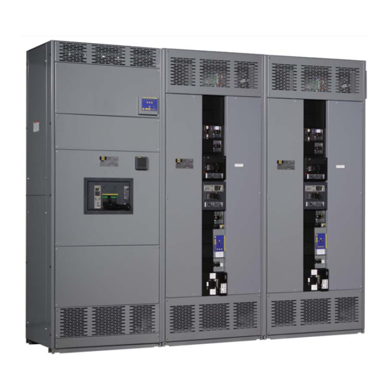
Square QED-2 Manuals
Manuals and User Guides for Square QED-2. We have
1
Square QED-2 manual available for free PDF download: Instruction Bulletin
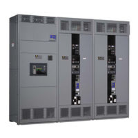
Square QED-2 Instruction Bulletin (188 pages)
Brand:
Square
| Category:
Switch
| Size: 6.61 MB
Table of Contents
English
5
Table of Contents
5
Section 1-Introduction
9
Inspection and Packaging
9
Document Replacement
9
Figure 1 - Typical QED-2 Roof Hood Construction
9
Section 2-Safety Precautions
10
Section 3-Receiving, Handling, and Storing
11
Receiving
11
Handling
11
Handling with Lifting Straps
11
Figure 2 - Lifting with an Overhead Crane, Lifting Straps, and Cables or Chains
11
Figure 3 - Handling Instruction Label, Switchboards Without Lifting Straps
13
Figure 4 - Rear Warning Label, Rainproof Switchboards
14
Figure 5 - Front Warning Label, Rainproof Switchboards
14
Storing
15
Section 4-Installation
16
Location
16
Foundation Preparation
16
Switchboard Preparation
17
General Installation
17
Joining Shipping Sections-Outdoor Switchboards
18
Joining Shipping Sections-Indoor Switchboards
19
Anchoring for Seismic Qualifications
20
Responsibility for Mitigation of Seismic Damage
20
Maintaining Seismic Certification
20
Figure 8 - Belleville Washer
21
Anchoring QED-2 Equipment for Seismic Applications
21
Base Anchoring
22
Table 1 - Enclosure X,Y, Z Dimensions in Inches (MM)
22
Figure 9 - Base Channel Floor Anchor Bolt Locations
23
Top Anchoring/Restraint
24
Figure 10 - Base Channel Mounting Hardware
24
Figure 11 - Top Anchor Hard-Point Locations
25
Figure 12 - Top Anchor Mounting Hardware
25
Anchoring the Switchboard
26
Through Bus Splice Connections
26
Figure 13 - Switchboard Base Channels
26
Ground Bus Splice Connections
27
Figure 14 - Proper Orientation of U-Shaped Splice Connector
27
Figure 15 - Ground Bus Splice Connection
27
Figure 16 - Series 2 Ground Bus Splice Connection
27
Grounding and Bonding
28
Service Equipment-Grounded System
28
Figure 17 - Grounding Electrode Connector
28
Figure 18 - Main Bonding Jumper
29
Figure 19 - Series 2 Main Bonding Jumper
29
Service Equipment-Ungrounded System
30
Not Service Equipment
30
High-Impedance Grounded Neutral Systems
30
Busway Connections
30
Busway Connection-NEMA Type 1 (Indoor) Only (Qwik Flange™)
30
Figure 20 - Qwik Flange Installation
31
Figure 21 - Qwik Flange
31
NEMA Type 3R
32
Figure 22 - Removing the Busway Dummy Flanged End
32
Figure 23 - Flanged-End Connections
32
Conduit Area
33
Figure 24 - Reinstalling the 1/2-In. (13 MM) Hardware
33
Cable Pulling
34
Cable Terminations
34
Cable Restraint for Short-Circuit Current Rating (SCCR)
35
Figure 25 - Cable Restraint Example
35
Table 2 - Cable Restraint Criteria
35
Figure 26 - Wrapping Cables (Neutral Cables Not Shown)
36
Figure 27 - Wrapping the Space between Cables
36
Figure 28 - Finish Wrapping the Space between Cables
37
Section 5-Pre-Energizing Checkout Procedure
38
Ground Fault Protection Systems
40
Section 6-Energizing the Switchboard
41
Section 7-Maintaining the Switchboard
42
General Inspection and Cleaning
42
Bus Bar Joints, Lug Terminations, and Insulating Materials
43
General Lubrication Information
43
Automatic Transfer Switches
43
Bolt-Loc Bolted Pressure Contact Switch Maintenance (800-4,000 A)
44
Figure 30 - Type BP Bolt-Loc Fusible Switch
44
Circuit Breakers
45
Figure 31 - Powerpact™ R-Frame Circuit Breaker
45
Table 3 - I-Line™ Blank Fillers and Extensions
46
Switch Maintenance
47
Fuse Replacement (Fusible Switches Only)
47
Installing QMB/QMJ/QMQB1 Fusible Switches
48
Table 4 - QMB/QMJ Fusible Switch Blank Fillers
48
Table 5 - QMQB1 Fusible Switch Blank Fillers
48
Removing QMB/QMJ/QMQB1 Fusible Switches
49
Ground Fault Protection Systems
49
Section 8-Adverse Circumstances
50
Inspection Following a Short Circuit
50
Clean-Up Following a Short Circuit
50
Water-Soaked Switchboards
50
Water-Sprayed or Splashed Switchboards (Clean Water Only)
51
Inspection and Clean-Up of Clean Water Sprayed or Splashed Switchboards
51
Section 9-Torque Values for Electrical Connections
53
Table 6 - Incoming, Branch, and Neutral Lug
53
Table 7 - Multiple Conductor Neutral And/Or Ground Bar
53
Section 10-Switchboard Insulation Resistance Chart
55
Section 11-Reference Publications
56
Section 12-Installation and Maintenance Log
57
Español
61
Figura 1 - Construcción Típica de la Cubierta Ventilada del Tablero QED-2
65
Inspección y Empaque
66
Reemplazo de Documentos
66
Sección 1-Introducción
65
Sección 2-Instrucciones de Seguridad
67
Sección 3-Recibo, Manejo y Almacenamiento
68
Recibo
68
Manejo
68
Figura 2 - Levantamiento con una Grúa Aérea, Correas de Levantamiento y
69
Cables O Cadenas
69
Manipulación sin Correas de Levantamiento
70
Figura 3 - Etiqueta de Instrucciones sobre la Manipulación de Los Tableros de Distribución sin Correas de Levantamiento
70
Figura 4 - Etiqueta de Advertencia en la Parte Posterior - Tableros de
71
Distribución a Prueba de Lluvia
71
Figura 5 - Etiqueta de Advertencia en la Parte Frontal - Tableros de Distribución a Prueba de Lluvia
71
Almacenamiento
72
Sección 4-Instalación
73
Ubicación
73
Preparación de Los Cimientos
73
Preparación del Tablero de Distribución Tipo Autosoportado
74
Generalidades sobre la Instalación
74
Unión de las Secciones de Transporte-Tableros de Distribución Tipo Autosoportado para Exteriores
75
Figura 6 - Unión de las Secciones Adyacentes-Tableros de Distribución Tipo
75
Unión de las Secciones de Transporte-Tableros de Distribución Tipo Autosoportado para Interiores
76
Figura 7 - Tableros de Distribución Tipo Autosoportado para Interiores
76
Sujeción para Obtener una Clasificación Sísmica
77
Responsabilidad con Respecto a la Reducción de Daños por Actividad Sísmica
77
Cómo Mantener la Certificación Sísmica
77
Figura 8 - Roldana Belleville
78
Sujeción de la Base de Montaje
79
Figura 10 - Herrajes para el Canal de Montaje
81
Figura 12 - Herrajes de Montaje para Sujeción en la Parte Superior
82
Sujeción del Tablero de Distribución Tipo Autosoportado
83
Figura 13 - Canales de Montaje del Tablero de Distribución Tipo Autosoportado
83
Conexiones de Empalme de las Barras de Paso
84
Figura 14 - Orientación Correcta del Conector de Empalme en Forma de U
84
Conexiones de Empalme de la Barra de Puesta a Tierra
85
Figura 15 - Conexión de Empalme de la Barra de Puesta a Tierra
85
Figura 16 - Conexión de Empalme de la Barra de Puesta a Tierra de la Serie 2
85
Unión y Puesta a Tierra
86
Equipo de Acometida-Sistema Puesto a Tierra
86
Figura 17 - Conector del Electrodo de Puesta a Tierra
86
Figura 18 - Puente de Unión Principal
87
Figura 19 - Puente de Unión Principal de la Serie 2
87
Equipo de Acometida-Sistema no Puesto a Tierra
88
Equipo no de Acometida
88
Sistemas con Neutro Puesto a Tierra con Alta Impedancia
88
Conexiones del Electroducto
88
Conexión del Electroducto-NEMA 1 (para Interiores) Solamente (con Brida Qwik Flange™)
89
Figura 20 - Instalación de la Brida Qwik Flange
89
Figura 21 - Brida Qwik Flange
90
Conexión del Electroducto-NEMA 1 (sin Brida Qwik Flange) y NEMA 3R
91
Figura 22 - Desmontaje de la Brida Falsa
91
Área Reservada para el Tubo Conduit
92
Figura 23 - Conexiones de la Brida
92
Figura 24 - Reinstalación de Los Herrajes de 13 MM (1/2 Pulg)
92
Extracción de Cables
93
Terminaciones de Cable
93
Sujetadores de Cables para la Corriente Nominal de Cortocircuito (SCCR)
94
Figura 25 - Ejemplo de Sujetador de Cables
95
Figura 26 - Cómo Enredar Los Cables (Los Cables de Neutro no Se Muestra)
96
Figura 27 - Cómo Enredar la Cuerda en el Espacio entre Los Cables
96
Figura 28 - Cómo Terminar de Enredar la Cuerda en el Espacio entre Los Cables
96
Figura 29 - Cómo Amarrar Los Extremos de la Cuerda
97
Sección 5-Procedimiento de Verificación de Pre-Energización
98
Sistemas de Protección contra Fallas a Tierra
101
Sección 6-Energización del Tablero de Distribución Tipo Autosoportado
102
Sección 7-Servicio de Mantenimiento
103
Inspección General y Limpieza
103
Juntas de las Barras de Distribución, Zapatas de Terminal y Material de Aislamiento
104
Información General sobre la Lubricación
105
Interruptores de Transferencia Automática
105
Mantenimiento de Los Desconectadores de Contacto a Presión Bolt-Loc (de 800 a 4 000 A)
105
Figura 30 - Desconectador Fusible Bolt-Loc Tipo BP
106
Interruptores Automáticos
107
Figura 31 - Interruptor Automático Powerpact™ Marco R
107
Tabla 3 - Placas y Extensiones de Relleno I-Line
108
Interruptores Fusibles QMB/QMJ/QMQB1
110
Servicio de Mantenimiento del Interruptor
110
Sustitución de Fusibles (Interruptores Fusibles Solamente)
110
Instalación de Los Interruptores Fusibles QMB/QMJ/QMQB1
111
Tabla 4 - Placas de Relleno para Los Interruptores Fusibles QMB/QMJ
111
Tabla 5 - Placas de Relleno para Los Interruptores Fusibles QMQB1
111
Desmontaje de Los Interruptores Fusibles QMB/QMJ/QMQB
112
Sistemas de Protección contra Fallas a Tierra
112
Sección 8-Circunstancias Adversas
113
Inspección Después de un Cortocircuito
113
Limpieza Después de un Cortocircuito
113
Tableros de Distribución Tipo Autosoportado Inmersos en Agua
113
Tableros de Distribución Tipo Autosoportado Rociados O Salpicados con Agua (sólo Agua Limpia)
114
Inspección y Limpieza del Tablero de Distribución Tipo Autosoportado Rociado O Salpicado con Agua Limpia
114
Sección 9-Valores de Par de Apriete para las Conexiones Eléctricas
116
Tabla 6 - Zapata de Entrada, de Derivación y de Neutro
116
Tabla 7 - Barra de Neutro de Conductores Múltiples Y/O de Puesta a Tierra
116
Sección 10-Tabla de Resistencia del Aislamiento
118
Sección 11-Publicaciones de Referencia
119
Sección 12-Registro Cronológico de Instalación y Servicios de Mantenimiento
120
Français
125
Chapitre 1-Introduction
129
Inspection Et Emballage
130
Remplacement de Documents
130
Chapitre 2-Mesures De Sécurité
131
Chapitre 3-Réception, Manutention Et Entreposage
132
Réception
132
Manutention
132
Manutention Avec Oreilles de Levage
133
Manutention Sans Oreilles de Levage
134
Entreposage
136
Chapitre 4-Installation
137
Emplacement
137
Préparation de la Fondation
137
Préparation du Panneau de Commutation
138
Installation Générale
138
Jonction des Sections de Transport-Panneaux de Commutation Pour Usage À L'extérieur
139
Jonction des Sections de Transport-Panneaux de Commutation Pour Usage À L'intérieur
140
Ancrage Pour Qualifications Sismiques
141
Responsabilité Concernant la Réduction des Dommages Sismiques
141
Maintien de la Certification Sismique
141
Ancrage de L'appareil QED-2 Pour Les Applications Sismiques
142
Ancrage de la Base
143
Ancrage du Panneau de Commutation
148
Raccordements de Jonction des Barres-Bus de Traversée
149
Raccordements de Jonction de la Barre-Bus de M.à.l.t
150
Mise À la Terre Et À la Masse
150
Appareil de Service-Système Mis À la Terre
150
Appareil de Service-Système Flottant
152
Appareil Non de Service
152
Systèmes de Neutre Mis À la Terre À Impédance Élevée
153
Raccordement À Une Canalisation Préfabriquée
153
Raccordement À la Canalisation Préfabriquée-NEMA 1 (Sans Qwik Flange) Et NEMA 3R
155
Zone Réservée Aux Conduits
156
Tirage des Câbles
157
Terminaisons des Câbles
157
Entrave des Câbles Pour Le Courant Nominal de Court-Circuit (SCCR)
158
Chapitre 5-Procédure Préliminaire de Mise Sous Tension
161
Systèmes de Protection Contre Les Défauts À la Terre
164
Chapitre 6-Mise Sous Tension du Panneau de Commutation
165
Panneaux de Commutation Power-Style MC QED-2
166
Chapitre 7-Entretien Du Panneau de Commutation
166
Inspection Générale Et Nettoyage
166
Joints de Barres-Bus, Cosses des Bornes Et Matériaux D'isolation
167
Informations Générales de Lubrification
168
Interrupteurs Automatiques de Transfert
168
Entretien des Interrupteurs À Contact Par Pression Bolt-Loc (800 À 4000 A)
168
Disjoncteurs
170
Entretien de L'interrupteur
172
Remplacement des Fusibles (Interrupteurs À Fusibles Uniquement)
172
Systèmes de Protection Contre Les Défauts À la Terre
174
Chapitre 8-Circonstances Indésirables
175
Inspection Après un Court-Circuit
175
Nettoyage À la Suite D'un Court-Circuit
175
Panneau de Commutation Imbibé D'eau
175
Panneaux de Commutation Aspergés Ou Éclaboussés D'eau (Eau Propre Uniquement)
176
Inspection Et Nettoyage de Panneaux de Commutation Ayant Été Aspergés Ou Éclaboussés Avec de L'eau Propre
176
Chapitre 9-Valeurs Des Couples de Serrage Pour Les Connexions Électriques
178
Chapitre 10-Registre Des Résistances D'isolation du Panneau de Commutation
180
Chapitre 11-Publications De Référence
181
Chapitre 12-Journal D'installation Et D'entretien
182
Advertisement
Advertisement
Related Products
Square Mini-VARIO
Square VARIO
Square Categories
Touch terminals
Card Reader
Racks & Stands
Motorized Toy Car
Payment Terminal
More Square Manuals
Login
Sign In
OR
Sign in with Facebook
Sign in with Google
Upload manual
Upload from disk
Upload from URL