Sign In
Upload
Manuals
Brands
Spectris Manuals
Measuring Instruments
Servomex SERVOPRO NanoChrome
Spectris Servomex SERVOPRO NanoChrome Manuals
Manuals and User Guides for Spectris Servomex SERVOPRO NanoChrome. We have
1
Spectris Servomex SERVOPRO NanoChrome manual available for free PDF download: Operator's Manual
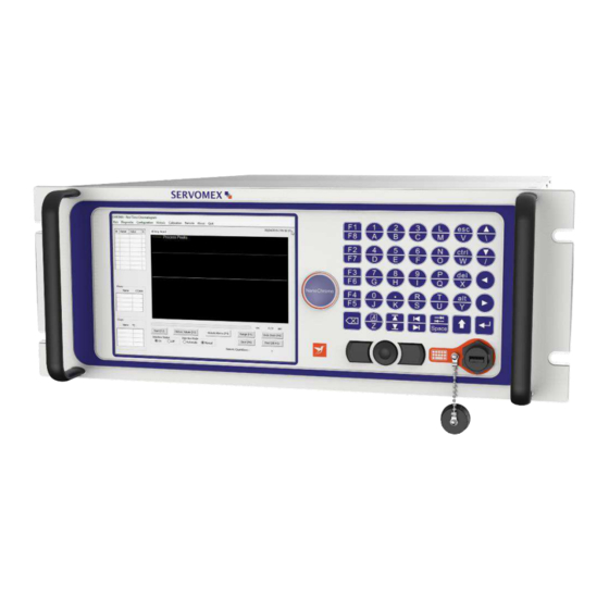
Spectris Servomex SERVOPRO NanoChrome Operator's Manual (124 pages)
Brand:
Spectris
| Category:
Measuring Instruments
| Size: 3 MB
Table of Contents
Table of Contents
3
Description and Definitions
9
Scope of this Manual
9
Safety Information
9
Description of Nanochrome Gas Analyser
10
Introduction
10
Plasma Emission Detector (PED)
11
Signal Conditioning
11
Main PC and Graphic Display
11
Oven Heater and Control
12
I/O Board
12
Table 1 : I/O Board
12
Description of Analyser Rear Connections
13
SERVOPRO Nanochrome Complete Rear Connector
13
Figure 1 : SERVOPRO Nanochrome Complete Rear Connections
13
SERVOPRO Nanochrome Reduced Rear Connections
14
Figure 2 : SERVOPRO Nanochrome Reduced Rear Connections
14
Auxiliary Oven
15
Description of Auxiliary Oven
15
Auxiliary Oven Rear Connections
15
Figure 3 : Auxiliary Oven Rear Connections
15
Standalone PC Rear Connections
16
Figure 4 : Standalone PC Rear Connections
16
Software License
18
Microsoft Software License Term
18
Specifications
29
General
30
Table 2 : General Specification
30
Gas
31
Table 3 : Gas Specification
31
Oven
32
Environmental Limits
32
Digital Relay Outputs
32
Table 4 : Oven Specification
32
Table 5 : Environmental Limits
32
Table 6 : Digital Relay Outputs
32
Ma Outputs
33
Digital Inputs
33
Table 7 : 4-20 Ma Outputs
33
Table 8 : Digital Inputs
33
Ethernet Port
34
Port
34
USB Connector
34
Table 9 : Ethernet Cable
34
Table 10 : RS-232 Port
34
Table 11 : RS-485 Port
34
Table 12 : USB Port
34
Mains Input Cables (Master/Secondary/Stand-Alone PC)
35
Table 13 : Mains Cable
35
The User Interface
36
User Interface Controls
36
Edit Box Control
36
Radio Control
36
Figure 5: Edit Box Control
36
Figure 6 : Radio Control
36
Slide Control
37
Push Button Control
37
Figure 7 : Slide Control
37
Figure 8 : Button Control
37
Grid Control
38
Combo Control
38
Figure 9 : Grid Control
38
Figure 10 : Combo Box Control
38
Check Box Control
39
Tab Control
39
Figure 11 : Check Box Control
39
Figure 12 : Check Tab Control
39
User Interface Menu Structure
40
Run Menu
40
Real Time Chromatogram Menu
40
Figure 13 : Menu Structure
40
Start Button (F2)
41
Figure 14 : Run - Real Time Menu
41
Injection Mode
42
Injection Status
42
Historic Values (F3)
42
Historic Alarm (F4)
42
Range (F5)
42
Save (F6)
43
Undo Zoom (F8)
43
Print (Alt F2)
43
Table 14 : Peak Grid - Alarm Status Display Colours
43
Remote Countdown
44
Historic Menu
44
Alarm Menu
44
Diagnostic Menu
47
Diagnostic
47
Figure 15 : Diagnostic Menu
47
Table 15 : Diagnostic Menu
49
Table 16 : Diagnostic Menu - Manual Checks
49
Analyse Chromatogram
50
Figure 16 : Diagnostic - Analyse Chromatogram
50
Table 17 : Diagnostic Analyse Chromatogram Menu
52
Trending
53
Figure 17 : Diagnostic - Trending Menu
53
Table 18 : Trending Menu - Summary of Functions
55
Figure 18 : Trending Menu Valve State
55
Advanced Diagnostic
56
Figure 19 : Diagnostic - Advanced Diagnostic Menu
56
Configuration Menu
58
System
58
Figure 20 : Configuration - System Menu
58
Table 19 : Oven Set Point
60
PID - Proportional Integral Derivative
62
Figure 21 : Configuration-PID Menu
62
Flow
63
Figure 22 :Configuration-Flow Menu
63
Cycle
64
Figure 23 : Configuration-Cycle Menu
64
Figure 24 : Cycle-Peak Configuration Menu
65
Table 20 : Peak Configuration Columns
66
Table 21 : Peak Data
66
Table 22 : Peak Configuration Menu
66
Figure 25 : Peak Detection Configuration Menu
67
Figure 26 : Integration Algorithm
67
Figure 27 : Peak Window Reduction
68
Figure 28 : Valve Configuration Menu
70
Figure 29 : Typical Sequence for Valve Timing
70
Figure 30 : Flow Timing Configuration Menu
71
Date & Time
72
Figure 31 : Date & Time Menu
72
Advanced Configuration
73
Figure 32 : Advanced Configuration - General Menu
73
Figure 33 : Advanced Configuration-Detector Menu
75
Figure 34 : Advanced Configuration-Flow Menu
76
Figure 35 : Advanced Configuration-Valve Menu
77
Figure 36 : Advanced Configuration - Oven Menu
78
Alarm
79
Figure 37 : Configuration-Alarm Menu
79
Printers
80
Figure 38 : Configuration-Printer Menu
80
Export the Analyser Configuration
81
Analyser Calibration
82
Noise Threshold (THRSH) Calibration
82
Figure 39 : Calibration-Calibration Menu
82
Span Calibration
83
Figure 40 : Calibration-Span Menu
85
Calibration of the 4-20Ma Outputs
87
Figure 41 : Calibration-4-20 Ma Outputs Menu
87
Remote
88
Report Software
88
Figure 42 : Remote Software Menu
88
Remote Control
89
Figure 43 : Remote-Remote Control Menu
89
About
90
Figure 44 : about Menu
90
Chromatogram Saving
91
Figure 45 : Historic-Chromatogram Saving Menu
91
Quit
92
Unpack the Analyser
93
Installation and Setup
94
Electrical Installation
94
Electrical Safety
94
Master Chassis Electrical Connections
95
Figure 46 : Master Chassis Electrical Connections
95
Master Chassis with Secondary Chassis Electrical Connections
96
Figure 47 : Master with Secondary Chassis, Electrical Connections
97
Figure 48 : Master with 2 Secondary Chassis, Electrical Connections
98
Stand-Alone PC with Secondary Chassis Electrical Connections
99
Figure 49 : Stand-Alone PC with Secondary, Electrical Connections
99
Figure 50 : Stand-Alone PC with Two Secondarys, Electrical Connections
101
Master/Secondary Chassis Rear Panel Electrical Connections
102
Digital Input
102
Digital Output Contacts
102
Table 23 : Digital Output Contacts
102
Figure 51 : Digital Input Connection
102
Ma Outputs
103
Figure 52 : Digital Outputs Connection
103
Port
104
Table 24 : 4-20 Ma Connections and Associated Fuses
104
Figure 53 : 4-20 Ma Schematic and External Connections
104
Port
105
Auxiliary Oven Port
105
Gas Installation
106
Choosing the Right Materials for the Sampling System
106
Carrier Gas Hardware Selection
107
Gas Connections - Rear Panel
108
Master and Secondary Chassis
108
Auxiliary Oven
108
Internal Dilution System Setup
109
Figure 54 : Internal Dilution System Schematic
109
Start-Up and Shutdown Procedure
111
Equipment/Tools
111
Installation Requirements
111
Start-Up Procedure
111
Shut-Down Procedure
113
Routine Maintenance
114
Storage and Disposal
115
Storage
115
Disposal
115
Compliance
116
Addendum
117
Start Analysis
117
Analyser Status
117
Table 25 : RS-232 Start Analysis
117
Table 26 : RS-232 Analyser Status
117
Send Results
118
Table 27 : RS-232 Send Results
118
Enable-Disable Calibration
119
Respan
119
Change Configuration
119
Table 28 : RS-232 Enable-Disable Calibration
119
Table 29 : RS-232 Re-Spanchange Configuration
119
Table 30 : RS-232 Change Configuration
119
Analyser Troubleshooting
120
Table 31 : Troubleshooting Typical Issues - Symptoms
120
Table 32 : Troubleshooting Typical Issues - Likely Causes
121
Table 33 : Troubleshooting Typical Issues - Potential Solutions
123
Product Disposal - Weee Directive
124
Reach Regulation
124
Figure 55 : the WEEE Label
124
Advertisement
Advertisement
Related Products
Spectris SERVOMEX SERVOPRO NOX
Spectris SERVOMEX SERVOPRO HFID
Spectris SERVOPRO Chroma
Spectris Servomex Servopro PureGas
Spectris Servomex OxyDetect
Spectris 04416001A
Spectris Bruel & Kjaer VCM-3
Spectris Bruel & Kjaer VIBRO Condition Monitoring 3
Spectris Malvern Panalytical MASTERSIZER 3000
Spectris Malvern Panalytical MASTERSIZER 3000E
Spectris Categories
Measuring Instruments
Accessories
Transducer
Cash Counter
Laboratory Equipment
More Spectris Manuals
Login
Sign In
OR
Sign in with Facebook
Sign in with Google
Upload manual
Upload from disk
Upload from URL