Sign In
Upload
Manuals
Brands
SKF Manuals
Measuring Instruments
Microlog GX-M
SKF Microlog GX-M Manuals
Manuals and User Guides for SKF Microlog GX-M. We have
1
SKF Microlog GX-M manual available for free PDF download: User Manual
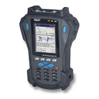
SKF Microlog GX-M User Manual (343 pages)
Data Collector/Analyzer Supports the GX Series Microlog System CMXA 75
Brand:
SKF
| Category:
Measuring Instruments
| Size: 10.51 MB
Table of Contents
General Product Information
2
Product Registration
2
Technical Support Group
2
Table of Contents
7
Introduction to the SKF GX Series Microlog
11
Safety Messages
11
Personnel Safety
11
Device Safety
11
Hazardous Locations
12
Avoid Battery Compartment Exposure
12
About this Manual
12
Chapter Overview
13
What Is the GX Series Microlog System?
14
LED Indicators
15
Microlog Application Modules
16
ROUTE Based Microlog Models
16
The GX-R Microlog
16
The GX-M Microlog
16
The GX-F Microlog
17
GX-A – the Base Model Microlog
17
@Ptitude Analyst Host Software
17
Skf's Analysis and Reporting Manager Software
18
The GX Series Microlog Main Menu Screen
19
Module Management
20
Hiding and Showing Icons
20
To Hide or Show Module Icons
20
Uninstalling Modules
21
Purchasing Additional Modules
22
GX Series Microlog Buttons and Keypad
22
Function Buttons
22
The Help Function
22
How to Use the Buttons and Keypad
23
GX Series Microlog Buttons and Keys
23
Power Button
24
Enter / Fire Buttons
24
Arrow Buttons
24
The Main Menu Screen
25
The Setup Screen
25
To Select a ROUTE
26
A Hierarchy List Screen
26
The Alpha/Numeric Keypad
27
0 / Shift Button
27
A Data Display Screen
27
Saving Microlog Screens Using the Keypad
28
Headphone Control Using the Keypad
28
To Print Your Saved Microlog Screen Bitmap
28
Battery Operations
29
Power Adapter/Battery Charger
29
Install and Charge the Microlog Battery
29
Battery Life
29
How to Install the Battery Pack
30
To Install the Lithium-Ion Battery Pack in Your Microlog
30
Replacing the Battery in an Active Microlog
30
How to Charge the Battery Pack
31
Battery Maintenance
31
To Charge a Battery Pack in the Microlog
31
Microlog System Connections
32
Communication Set up
32
Connectors on Top of the Microlog GX
32
CH1, CH2, USB Device/Power/Trigger, and USB Host Connectors
33
Wrong and Correct Way to Disconnect Microlog Cables
33
Connector Details
34
Mating Connector Details
34
Microsoft Activesync Communications
35
Installing Activesync, or Mobile Device Centre
35
USB Drivers for Microlog
35
To Install the Driver Files
35
SD Memory Card Operation
37
SD Card Memory Advantages
37
Hardware Installation
37
How to Perform a Reset on Your Microlog
38
To Perform a Soft Reset
38
To Hard Reset Your Microlog
38
Strap Attachment
39
GX Series Microlog Specifications
39
Input Sources
39
Preprocessing
40
Data Processing and Storage
40
Measurement
40
How to Set up Your GX Series Microlog
43
System Settings
43
To Access the Setup Screen
43
Autorange
45
Sensor Units
45
Speed Measurement
45
Filter Entry
46
Trigger
46
Module ICP
47
Date Format
47
Time Zone
47
Memory
47
Audio Output Status
48
Transducer Change
48
Bias Check
48
Nonroute
48
Global Measurement Settings
49
To Access the Instrument Configuration Screen
49
Instrument Configuration Screen Settings
49
The Instrument Configuration Screen
49
Display Update
50
Auto Advance
50
Dither Time
50
Machine Speed
50
Route ICP
51
View MPA Spectrum
51
Trigger Level
51
Sensor Setup
52
Hist. Data Collect
52
To Access the Sensor Setup Screen
52
The Sensor Setup Screen
53
An Add Sensor Screen
54
To View an Existing Sensor Configuration
54
Troubleshooting
55
Memory Operations
55
A View Sensor Screen
55
The ROUTE Module
57
Overview
57
What Is a ROUTE?
57
How to Download and Upload Routes and ROUTE Data with the GX Series Microlog
58
Microlog Transfer Overview
58
A Note about Host Software Fmax Values
59
Selecting Operators
59
The Route Manager
59
How to Collect ROUTE Measurements
60
How to Navigate the ROUTE Hierarchy List
60
Example of a ROUTE Hierarchy List (with Access to Nonroute Module)
61
A Note about the Auto Advance Setting
63
How to Begin Route Data Collection
63
To Begin ROUTE Data Collection
63
The ROUTE Mode Screen
64
To Open a Machine and Collect Data
64
A Spectral Measurement Display
65
ROUTE Status Display
66
Viewing Dynamic Measurement Data
66
Viewing Spectral Data
66
A Spectrum Display Screen
67
Percent Changed Bar with Overall Overflow
68
Harmonic Markers
70
Peak Cursor
70
Viewing Time Waveform Data
70
Y-Axis Graph Scaling Adjustment
70
A Tiled Spectrum and Time Waveform Screen
71
A Time Waveform Display Screen
72
A Triax Spectrum Display Screen
73
Viewing Multi-Channel Data
73
An Orbit Display Screen
74
Viewing Orbit Data
74
How to Collect Process Measurements
75
Process Measurement Pickup Entry
75
To Access the Process Measurement Data Screen
75
A Process Measurement Data Screen
76
Manual Process Measurement Entry
77
To Manually Enter Process POINT Data
77
How to Attach Coded Notes
78
The Coded Notes Text Entry Screen
78
To Access the Notes Screen
78
Speed Ratio
79
Speed Tagging
79
Microlog
80
Using a Temporarily Attached Pickup
80
Hints for Efficient Data Collection
81
Input Range
81
MPA POINT Rules
82
Multi Point Automation (MPA)
82
Spectral Banding
82
MPA Group Data Collection
83
MPA ROUTE Setup
83
To Begin MPA Group Data Collection
83
How to Review Collected Data
84
How to Review Dynamic Measurement Data
84
The MPA Collecting Data Screen
84
How to Review Orbit Data
86
An MPA Spectral Display Review Screen
87
How to Review Multi-Measurement Data
87
To Review Multi-Measurement Data
87
Earlier / Later Function Buttons
88
How to Review Historical Data
88
Historical Data – Waterfall View
89
To View Historical Data as a Waterfall Plot
89
How to Review Process (Static) Measurement Data
90
To Review a Process Measurement Point’s Data
90
The Analyzer Module
91
Overview
91
The Analyzer Screen
92
Standard Vibration Measurements Include
92
How to Collect Standard Vibration Measurements
93
Collecting Measurements Using the Default Measurement Setup
93
Example Analyzer FFT Measurement Display Screen
94
To Change to a Different View
96
An Example Table of Peaks Display
96
Selecting a View Option
96
A Measurement’s Power Spectrum View
97
How to Change the Measurement Setup before Performing Measurement
98
The Acceleration Measurement’s Setup Screen (Reduced View)
98
To Expand the Measurement Parameter List
99
Analyzer Measurement Setup Fields
99
The Acceleration Measurement’s Setup Screen (Expanded View)
99
Sensitivity
100
ICP Supply
100
View Signal
100
Y-Axis Units
100
Detection
101
Lines
101
Avg. Type
101
Num. Averages
101
Window
102
Hanning
102
Hamming
102
Flattop
102
Example Analyzer Time Waveform Measurement Display Screen
103
How to Save, View, and Delete Analyzer Measurement Results
104
To Save Analyzer Measurement Results
104
An Example Analyzer – Save Data Screen
104
Back - the Analyzer
105
How to View Stored Measurement Results and Measurement Setups
106
An Example Analyzer – Load Setup Screen
106
How to Backup Stored Spectra
107
Copying Spectra to the Host Computer
107
Backing up Spectral Data to an SD Card
107
How to Delete Stored Files
108
To Delete All Files / Folders
108
The Delete All Screen
108
How to Perform Multi-Channel Measurements
109
Multi Channel Measurement View Signal Options
109
Notes about Phase Measurements
109
Special Considerations When Taking Multi-Channel Measurements
110
Measurement Setup
111
To Set up and Collect Analyzer Multi-Channel Measurements
111
The New Measurement Setup Screen (Reduced View)
111
Multi-Channel Measurement Setup Fields
112
Multi-Channel Measurement Displays
113
Two Channel Spectral Displays
113
A Two Channel Spectral Display Screen
113
Two Channel Time Displays
114
A Two Channel Time Waveform Display Screen
114
Two Channel Spectrum+Time Displays
115
Two Channel Spectrum & Phase Displays
116
Two Channel Spectrum+Cross-Channel Phase Displays
117
A Two Channel Spectrum+Cross-Channel Phase Display Screen
117
Triax Displays
118
Multi Channel Cursor, Display Expand, and Full Scale Adjustments
118
A Triax Spectral Display Screen
118
Independent Autoranging
119
How to Measure Shaft Orbit
119
Orbit Overview
119
How to Take Orbit Data
119
Orbit View Options
120
A Raw (Unfiltered) Orbit Display
120
A Filtered 1X (First Order) Orbit Display
121
The Orbit Default Setup Screen (Expanded View)
121
Orbit Measurement Setup Fields
122
How to Perform a Bump Test
123
Why Do a Bump Test?
123
To Perform the Bump Test Using the Default Setup
123
An Initial Bump Test Display
124
A Bump Test Display after a Hammer Hit
124
Bump Test View Options
125
To Change the Bump Test Measurement’s Settings
125
To Alter the Measurement’s Setup and then Perform the Measurement
125
Bump Test Measurement Setup Fields
126
How to Perform Motor Current Measurements
126
To Perform a Motor Current Test
126
To Perform the Motor Current Test Using the Default Setup
126
A Motor Current Test Display.
127
To Change the Motor Current Measurement’s Settings
127
Motor Current Measurement Setup Fields
128
Machinery Balancing Module
129
Microlog Balancing Overview
129
Single-Plane Balancing Overview
129
Measurement Trigger Requirements
129
Perform the Reference Run
130
Attach a Trial Weight
130
Perform the Trial Run
130
Attach the Permanent Correction Weight
130
How to Set up the Microlog for a Single-Plane Procedure
131
To Initiate the Balancing Application
131
The Balancing Menu Screen
131
Perform a Trim Run
131
The Balance Setup Screen
132
Balance Setup Screen Fields
133
How to Perform a Single-Plane Procedure
136
To Begin the Single-Plane Balancing Procedure
136
The Initial Balancing Summary Screen
136
An Example Balancing Summary Screen Showing Multiple Runs
137
The Initial Run Screen with Data Displayed
138
The Initial Run Screen (Polar Version)
139
To Save the Balancing Job from the Summary Screen
141
A Balancing Summary Screen with Initial Run (IR) Data
141
Add a Trial Weight
142
The Trial Weight Screen
142
How to Estimate Trial Weights
143
To Estimate the Trial Weight
143
An Estimated Trial Weight Screen
143
The Trial Run Screen (Bar Chart Version)
144
The Trial Run Screen (Polar Version)
144
Performing Multiple Trial Runs (Optional)
145
To Perform Multiple Trial Runs
145
The New Trial Run Message
146
Example of Multiple Trial Runs
147
To Proceed with the Balancing Job
147
Add the Correction Weight
148
The Correction Weight Screen
148
The Actual Correction Dialog
149
A Residual Unbalance Message
150
Perform a Correction Weight Run
151
To Proceed with a Trim Run(S) (also Called Check Run(S))
151
Two-Plane Balancing Procedure Overview
152
Set up Balancing Equipment and Measurement Parameters
152
Perform the Reference Runs
152
Attach Trial Weight to Plane 1
152
Perform the Trial Run on Plane 1
153
Perform the Trial Run on Plane 2
153
Attach the Trial Weight to Plane 2
153
Attach the Permanent Correction Weights
153
How to Set up a 2 Plane Procedure
154
The 2-Plane Balance Setup Screen (Reduced View)
154
Setup Options Specific to 2 Plane Balancing
155
How to Perform a Dynamic 2 Plane Procedure
155
The 2-Plane Initial Run Screen with Data Displayed
157
Add a Trial Weight to Plane a
159
Perform the Trial Run for Plane a
160
Plane A’s Trial Run Screen (Polar Version)
160
Add a Trial Weight to Plane B
161
Plane B’s Trial Weight Screen
161
Perform the Trial Run for Plane B
162
Plane B’s Trial Run Screen (Polar Version)
162
The Correction Weight CW 1 Screen
163
Plane A’s Correction Run Screen Displaying Residual Unbalance
164
To End the Balance Job
165
How to Perform a 1-2 Plane with Prognosis Procedure
166
The Prognosis
171
Add a Correction Weight to Plane a
172
Balancing Using the Strobe Light
175
To Increase the Signal to the Strobe
176
Data Recorder Module
177
Overview
177
How to Perform a Data Recorder Measurement
178
Collecting Recorder Measurements Using the Default Measurement Setup
179
Previewing the Measurement
179
Recording the Measurement
180
Data Recording in Process
180
The Recorder – Save Data Screen
181
The General Measurement’s Setup Screen (Expanded View)
182
Recorder Measurement Setup Fields
183
Run up / Coast down Module
185
Overview
185
How to Set up a RUCD Measurement
186
Typical RUCD Measurement Setup
186
The RUCD Screen
187
RUCD LED Indicators
188
RUCD Setup Fields
188
The RUCD Taking Data Screen
190
Recording the Measurement
190
Displaying Acquired Data
191
The Display Select Menu
191
Bode Plot Display
192
Bode Plot Setup
192
The Bode Setup Screen
192
Nyquist Plot Display
195
Nyquist Plot Setup
195
An Example Nyquist Plot with Three Traces Displayed
196
Display
197
Display Setup
197
The Table Setup Screen
197
An Example Table Display
198
Waterfall Plot Display
199
Waterfall Analysis Setup
199
The Waterfall Setup Screen
199
The Waterfall Display Setup Menu
200
Example of Z-Axis Timestamp, Even, and RPM Spacing
201
Example No. Spectra Settings of 20 and 38
201
Spectrogram Plot Display
207
Spectrogram Plot Setup
207
The Spectrogram Setup Screen
207
The Spectrogram Display Setup Menu
207
Example of Z-Axis Even, Time and RPM Spacing (Left to Right)
208
Example Blanking Settings of 0% and 1% (Left to Right)
208
Example Spectrogram Plot
209
Spectrogram “Display Status” Indicators
209
Spectrogram “Display Status” Area
209
Cursor Movement
210
Saving, Reviewing, and Deleting Measurements
210
Saving RUCD Data
210
Frequency Response Function Module
211
Additional Background Information
211
Newton’s Law and Apparent Mass
211
Overview
211
How to Set up an FRF Measurement
212
Test Apparatus Setup
212
Example FRF Measurement Setup
212
To Set up the FRF Test Apparatus
213
FRF Module Setup
213
The FRF Menu Screen
214
FRF Analysis Setup Fields
215
The FRF New Measurement Setup Screen (Expanded View)
215
Recording the Measurement
217
The Automatic Parameter Setup Prompt
218
FRF - Taking Data Mode - Automatic Parameter Setup Hit Count
218
The Automatic Parameter Setup Results
219
Example of Taking Data Mode
220
Verify Acquired Data
221
The Taking Data Screen – Final FRF
221
Field Calibration
222
Set-Up Field Calibration
222
Example of Set-Up for Field Calibration
222
Saving FRF Data
223
Field Calibration Set-Up Fields
223
Conformance Check Module
225
Overview
225
How to Transfer Test Templates to the Microlog GX
226
To Transfer Test Template Files to the Microlog GX
226
Activesync’s Connected / Synchronized Message
226
How to Set up or Customize Conformance Test Templates
228
The Microlog Gx’s Template Selection Screen
228
To Set up a Custom Test Template
228
The Conformance Check Setup Generator Application’s Opening Screen
229
The CC Setup Application’s Setup Tabs
229
“Measurement” Tab
230
“Measurement - Transducer” Sub-Tab
230
Measurement – Transducer Configuration Tab
230
“Measurement - Measurement Control” Sub-Tab
232
“Machine Picture” Tab
233
Example of a Specified Machine Picture
233
“FFT Control” Tab
234
FFT Control – Normal (Baseband) Tab
234
“Grade Labels” Tab
236
Example Grade Label Settings
236
“Grade Bands” Tab
237
“Grade Boundaries” Tab
239
How to Perform a Conformance Survey
240
How to Save “Test Template” Settings
240
Test Templates in the Custom Setups Folder
241
The Measurement Results Screen
242
A Machine Graphic Indicating Measurement Locations
242
Example Conformance Test Results
243
Example Showing All Measurement Results
244
Example Showing Measurement Values
244
Survey Warning Messages
245
How to Save Your Test Results
245
Saving Conformance Check Data
246
Spindle Test Module
247
Overview
247
SKF Spindle Assessment Kit – Required Tools
248
How to Perform a Survey
248
How to Transfer Test Templates to the Microlog
248
The Home Screen’s Spindle Test Icon
249
Test Template Folder Icons
249
Spindle Tests Overview
252
Imbalance Test Overview
252
To Perform an Imbalance Test
252
Imbalance Test Setup Screens
253
Preset Vibration Measurements
253
Mechanical Condition Test Overview
254
To Perform a Mechanical Condition Test
254
Mechanical Condition Test Setup Screens
254
Bearing Condition Test Overview
255
To Perform a Bearing Condition Test
255
Select the Speed Range for the Spindle
256
Execute Preset Enveloped Acceleration Vibration Measurements
256
Nose Run-Out Test Overview
257
To Perform a Nose Run-Out Test
257
Enter Run-Out Range Value
258
Indicator Position
258
Clamp Force Test Overview
259
Run-Out Test Results
259
Perform a Clamp Force Test
259
Clamp Force Test Setup Screens
260
Enter the Average Value
260
Clamp Force Test Results
261
EM Distance Test Overview
262
To Perform an EM Distance Test
262
EM Test Setup Screens
262
EM Test for HSK and ISO
262
Measure with a Depth Micrometer
263
Enter the EM Test Value
263
Belt Tension Test Overview
264
To Perform a Belt Tension Test
264
Belt Tension Test Setup Screens
264
Enter the Result
265
Belt Test Results
265
Speed Accuracy Test Overview
266
To Perform a Speed Accuracy Test
266
Monitor the Speed with a Tachometer
266
Resonant Frequency Test Overview
267
Speed Accuracy Test Setup Screens
267
RUCD – Waterfall Plot
268
Resonance Frequency Test Results
268
Balancing Overview
269
To Perform a Balancing Test
269
Survey Warning Messages
269
How to View Stored Test Results
270
The View Stored Measurements Screen
270
How to Backup Stored Survey Results
271
Copying Survey Results to the Host Computer
271
Results Import Tool
271
Backing up Survey Results to SD Card
271
How to Delete Stored Surveys
272
Shifted Function Buttons Showing Backup / Delete Options
272
Idler Sound Monitor Module
273
Conveyor Idler Rollers
273
Overview
273
Measurement Overview
275
Example of Idler Measurement Data Displayed in Microsoft Excel
276
Saving Idler Sound Monitor Data
276
Conveyor Survey Overview
277
Hardware Setup
277
Attaching the Microphone to the Parabolic Reflector
278
The Microphone and Cable in Handle Housing
278
To Attach the Microphone Inside the Parabolic Reflector
278
Attaching the Microphone / Parabolic Reflector to the Microlog
279
Hand Held Method
279
Shoulder Mount Method
279
Microlog with Adapter Plate Assembly Attached
280
To Attach the Adapter Plate Assembly
280
To Attach the Microphone / Parabolic Reflector to the Adapter Plate
280
Fitting the Wind Baffle
281
Parabolic Reflector with Wind Baffle
281
The Microphone/Parabolic Reflector Connected to the Microlog
281
Attaching the Headphones
282
Connecting Headphones and Adjusting Headphone Volume
282
How to Set up a Conveyor Idler Survey
283
The Idler Sound Monitor Main Menu
283
The New Idler Monitor Measurement Screen
284
Idler Sound Monitor Setup Fields
285
How to Perform a Conveyor Idler Roller Survey
286
Optimal Survey Conditions
286
To Start the Conveyor Survey
286
Measurement Results Display
287
The ISM Module’s Idler Condition Indicator Displays
288
How to Digitally “Note” Faulty Idler Rollers
289
To Digitally “Note” a Faulty Idler
289
An Example Analysis Display
290
How to Analyze Faulty Idler Rollers
290
To View Individual Measurement Results and Alarm Status
290
How to Load a Saved Idler Sound Monitor Setup
291
How to Transfer and Review Survey Data Files on Your PC
291
To Copy Data Files to the Host PC
291
Transferring, Reviewing, and Deleting Survey Data Files
291
How to Delete Stored Survey Data Files on the Microlog
292
Backing up Data to an SD Card
293
Example of Survey Setup and Survey Data Files Stored in the Microlog
293
Procedure for Determining Specific Conveyor Alarm Threshold Settings
294
Resetting Measurement Alarm Thresholds
294
Non ROUTE Mode Operations
295
Overview
295
To Access Non ROUTE Mode
295
Non ROUTE Mode
296
High Resolution
297
How to Collect Pre-Set Non ROUTE Measurements
297
Opposite
297
Orbit Operation
299
To Quickly Perform One of the Pre-Set Measurements
299
Orbit Measurement Setup
300
The Orbit Setup Screen
300
To Set up and Collect a Non ROUTE Orbit Measurement
300
Collecting Data Screen with Running Speed Options
301
To Manually Enter the RPM
301
Collecting and Displaying Orbit Data
302
The Enter RPM Plot Display Screen
302
An Orbit Display
303
How to Collect “User” Defined Non ROUTE Data
304
The Nonroute User Defined Measurement Setup Screen
304
To Set-Up a User Defined Non ROUTE Measurement
304
To Specify Your Measurement’s Parameters
305
User Defined Measurement Options
305
How to Set up HFD Measurements
309
How to Set up Multi-Channel Measurements
310
Multi Channel Measurement Options Overview
310
Setting up Non ROUTE Dhfd Points
310
Microlog Setup
311
How to Set up a Cross Channel Phase Measurements
316
Collecting and Displaying Cross-Channel Phase Data
317
The Spec Spectral Display Screen
317
A Cross Channel Phase Data Display Screen
318
Multi Channel Cursor, Display Expand, and Full Scale Adjustments
318
How to Review Non ROUTE Measurement Data
319
Triggerless Operation
319
The Non ROUTE Review Screen
320
To View the Non ROUTE Measurement’s Pt. Info Screen
320
To View the Non ROUTE Measurement’s Review Data Screen
320
Field Upgrades and Accessories
321
Overview
321
Using the Headphones and Strobe Light
323
How to Use the Headphones with the GX
323
Connecting the Headphones to the GX Series Microlog
323
How to Use the Strobe Light with the GX
324
Connecting the Strobe Light to the GX Series Microlog
324
Strobe Light Connected to GX Series Microlog
324
Safety Instructions
325
Accelerometers
325
Batteries
325
Instrument Installation Drawing (090-22600-1 Rev B)
325
Connecting an Accelerometer to the Instrument
326
Instrument Installation Drawing (090-22600-1 Rev B
326
Memory Cards
327
Safety Instructions (090-22861-1 Rev C
328
Optical Speed/Phase Sensors
330
Straps
330
Glossary of Terms
331
Index
335
Advertisement
Advertisement
Related Products
SKF Microlog GX Series
SKF Microlog GX-R
SKF Microlog GX-F
SKF Microlog GX-A
SKF Multilog WVT
SKF Multilog IMx-S Series
SKF Multilog On-line System IMx-T
SKF MicroDosage System
SKF SKF-MPB-PUMP-1 Series
SKF 15V-090-00082-100
SKF Categories
Water Pump
Measuring Instruments
Lubrication systems
Tools
Industrial Equipment
More SKF Manuals
Login
Sign In
OR
Sign in with Facebook
Sign in with Google
Upload manual
Upload from disk
Upload from URL