Sign In
Upload
Manuals
Brands
SKF Manuals
Measuring Instruments
Baker AWA-IV 12 HO
SKF Baker AWA-IV 12 HO Manuals
Manuals and User Guides for SKF Baker AWA-IV 12 HO. We have
1
SKF Baker AWA-IV 12 HO manual available for free PDF download: User Manual
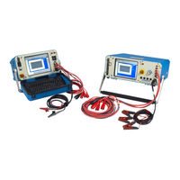
SKF Baker AWA-IV 12 HO User Manual (214 pages)
Static Motor Analyzer
Brand:
SKF
| Category:
Measuring Instruments
| Size: 9.09 MB
Table of Contents
Fort Collins, CO
5
Table of Contents
15
1 About this Manual
21
Formatting
21
Information Devices
21
2 Safety and General Operating Information
23
Symbols on Equipment
23
Labels on Equipment
23
Safety Precautions
24
Test Related
24
General
25
Emergency Stop Button
26
Baker ZTX E-Stop and Remote E-Stop
27
General Operation, Maintenance, and Service Information
28
Cleaning and Decontamination
28
Technical Assistance / Authorized Service Centers
28
Unpacking the Unit
28
Pollution Degree II
28
Power Requirements
28
Environmental Conditions
29
Power Pack Lifting and Shipping
29
Lifting the Instrument
29
Operating and Shipping Positions
30
3 Database Management and Maintenance
31
Database Management
31
Consequences of Not Organizing Data
31
Starting the Software
32
Creating a New Database
32
Opening an Existing Database
33
Using Multiple Databases
34
Data Transfer Feature
35
Transferring Motor and Test Results Data
35
Transferring Test Ids
38
Archiving a Database
39
Restoring a Database
40
4 Baker AWA-IV Instrument Overview
43
Baker AWA-IV 2 Kv/4 Kv Model Front Panel
43
VGA Port
43
USB Ports
43
Ethernet Connector
43
Emergency Power Shut-Off
44
Resistance Leads
44
High-Voltage Test Leads
44
Voltage Output Control Knob (6 Kv and 12 Kv Models Only)
44
Baker AWA-IV 6 Kv/12 Kv Model Front Panel
44
Baker AWA-IV 6 Kv Model Distinctions
45
Setting up the Baker AWA-IV Tester
45
Selecting an Optimal Environment
45
Making Basic Connections and Starting the Analyzer
45
Connecting Test Leads to Motor under Test
46
Configuring a Printer
46
Using the Footswitch
46
5 Baker AWA-IV Software Overview
47
Starting the Software
47
Creating a New Database
48
Opening an Existing Database
49
Using Version 4 Software for the First Time
50
Main Window
51
Main Menu
52
File Menu
52
View Menu
53
Database Menu
54
Window Menu
54
Tools Menu
55
Help Menu
55
Toolbar
56
Tabs
57
Explore Tab
57
Motor ID Tab
58
Route Tab
59
Modifying the Display of Lists in the Motor ID and Route Tabs
61
Viewing Test Data
62
Using the Data Tab
63
Motor Location Fields
64
Motor ID Field
64
Data Tab-Nameplate View
65
Data Tab-Application View
67
Data Tab-Results Summary View
69
Data Tab-Surge View
70
Data Tab-PI View
72
Data Tab-Step/Ramp-Voltage View
73
Using the Tests Tab
75
Test Configuration
76
Temperature/Resistance Test Setup Window
76
Manually Entering Resistance Measurements
79
DC Tests Setup Window
80
Surge Test Setup Window
83
E Bar Graph
85
Creating a Surge Test Reference
86
Viewing Surge Test Results
90
Using the Trending Tab
91
Max Delta R
92
Resistance Trending Graphs
92
Insulation Resistance/Megohm
93
Hipot
94
Relative Humidity
95
Special Software Trending Features
95
6 Test Procedures
97
Before Testing Begins
97
Recommended Testing Sequence
97
Balance Resistance Test or Line-To-Line Resistance
98
Megohm Test
98
DA/PI Test
98
Hipot Test
99
Step Voltage Test
99
Surge Test
99
Recommended Test Voltages for Insulation Resistance Testing
100
Recommended Test Voltages for Hipot and Surge Tests
100
Performing an Example Test
101
Creating a Motor ID
101
Creating a Test ID
103
Configuring Temperature/ Resistance Test
105
Configuring DC Tests
107
Configure Surge Test
109
Running an Automatic Test
111
Reviewing Test Results/Data
115
Printing Reports
118
Creating a New Motor Voltage Class
123
Surge Testing Notes and Recommendations
124
Surge Testing with Rotor Removed (Typically Motor Shop Testing)
124
Surge Testing with Rotor Installed (Typically Field Testing)
124
Surge Testing DC Motors
124
False P-P EAR Failures
124
Surge Test Underpowered
124
Surge Testing through Capacitors
125
7 Special Features of the Baker AWA-IV
127
Predictive Maintenance
127
Quality Control
128
Motor Troubleshooting
128
Field Coils
128
Hi L in Baker AWA-IV 2 Kv and Baker AWA-IV 4 Kv
129
Using the Hi L Technique
130
Fine Tuning the Technique
131
8 Using Power Packs with 6/12 Kv Models
137
Power Pack Setup
138
Operating Position
138
Combining Baker AWA-IV Host and Power Pack Tests
139
Creating Ids and Setting up the Test
139
Running the Combined Baker AWA-IV and Power Pack Tests
142
Testing with the Baker PP30 Three-Phase Test Lead Power Pack
144
Conducting DC Tests with the Baker PP30 Three-Phase Test Lead Power Pack
145
Conducting Surge Tests with the Baker PP30 Three-Phase Test Lead Power Pack
147
Testing with the Baker PP24 Single-Phase Test Lead Power Pack
150
Conducting DC Tests with the Baker PP24 Single-Phase Test Lead Power Pack
150
Conducting Surge Tests with the Baker PP24 Single-Phase Test Lead Power Pack
151
9 Using the Baker ZTX with Baker AWA-IV Analyzers
153
Principles of Armature Insulation Testing
153
Connecting Baker AWA-IV to the Baker ZTX Accessory
154
Armature Preparation
155
Configuring a Surge Test for Armature Bar-To-Bar Testing
156
Reviewing Test Results/Data
162
Printing Reports
164
Generating CSV Files
165
Appendix A - Baker AWA-IV Troubleshooting
167
Self-Help and Diagnostics
167
Repair Parts
167
Step #1: Basic Information
167
Step #2: Applications or Service Problem
168
Applications: What to Do First
168
Common Application Problems
168
Service: What to Do First
170
Open Condition Display
170
Hipot Display Checks
170
Open Ground Check
171
Answer These Questions
171
Limited Output Surge Waveform
171
Proper Storage of Leads/Unit
172
Checking Test Leads for Broken Sections
172
Manual Break Check
172
Overcurrent Trip Test
172
Open Circuit Test to Verify Analyzer Operation
172
Third-Party Software Warning
173
Warranty Return
174
Warranty Return Form
174
Appendix B - Technical Specifications and Applicable Standards
175
Calibration Information
175
Baker AWA-IV 2 Kv and 4 Kv Tester Specifications
175
Baker AWA-IV 6 Kv, 12 Kv, and 12 Kvho Tester Specifications
177
Applicable Standards
179
Appendix C - Database Definition
181
Version 4.0 Database Definition
181
Nameplate Table-(Motorid)
181
Test Results Table-(Testresults)
182
Memo Table-(Memo)
186
Polarization Index Test Results Table-(Testresultspi)
187
Step Voltage Test Results Table-(Testresultsprghipot)
189
Surge Test Results Table-(Surgewaveform)
190
Test Results Parameters Table-(Testresultsparameters)
191
Test ID Table-(Testid)
195
Step Voltage Test ID Table-(Testidprghipot)
199
Reference Surge Waveform Table- (Refsrgwaveform)
200
Database Information Table-(Databaseinfo)
201
Work List Table-(Route)
201
Motor Voltage Class Table-(Motorvoltageclasses)
201
Appendix D - Baker AWA-IV Specific Winding Faults
203
Software Fault Messages
203
Resistance Failure Types
203
DC Test Failure Types
204
Surge Test Failure Types
204
Fault Analysis Chart
205
AWA-IV Static Testing Parameters, Indicators, and Common Causes
205
Index
207
Advertisement
Advertisement
Related Products
SKF Baker AWA-IV 12 kV
SKF SSVL 10-K
SKF SSVL 12-K
SKF SSVL 14-K
SKF SSVL 10/9-V1
SKF SSVL 12/11-V1
SKF SSVL 14/13-V1
SKF 15V-090-00082-100
SKF CMAS 100-SL
SKF 15V-090-00102-200
SKF Categories
Water Pump
Measuring Instruments
Lubrication systems
Tools
Industrial Equipment
More SKF Manuals
Login
Sign In
OR
Sign in with Facebook
Sign in with Google
Upload manual
Upload from disk
Upload from URL