Sign In
Upload
Manuals
Brands
Siemens Manuals
Power Supply
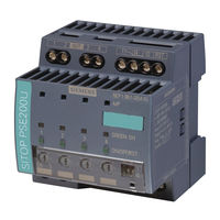
SITOP PSE200U
Siemens SITOP PSE200U Manuals
Manuals and User Guides for Siemens SITOP PSE200U. We have
4
Siemens SITOP PSE200U manuals available for free PDF download: Manual
Siemens SITOP PSE200U Manual (99 pages)
Integration of a SITOP 24 V power supply in PCS 7
Brand:
Siemens
| Category:
Power Supply
| Size: 5.43 MB
Table of Contents
Legal Information
2
Table of Contents
3
1 Introduction
5
Overview
5
Automation Task
6
Principle of Operation
6
Components Used
9
2 Basics
10
Sitop Psu8200
10
Sitop Pse202U
11
SITOP UPS1600 with UPS1100
12
Sitop Pse200U
14
Power Supply System SITOP PSU8600
15
3 Prepare SITOP Library
18
4 Redundant 24 V DC Power Supply
20
Setting up the Hardware Configuration
21
Copying Process Tag Types
22
Creating an as Program
23
Parameterizing Messages
25
Creating a Process Picture
26
Runtime
27
5 Uninterruptible 24 V Power Supply
28
UPS1600 on PROFINET IO Field Bus
28
Setting up the Hardware Configuration
28
Copying Process Tag Types
34
Creating an as Program
35
Messages
36
UPS1600 with Monitoring of the Signal Contacts
37
Setting up the Hardware Configuration
38
Copying Process Tag Types
38
Creating an as Program
40
Parameterizing Messages
43
Creating a Process Picture
44
Runtime
45
6 Selective Monitoring of 24V Feeders
47
Setting up the Hardware Configuration
48
Copying Process Tag Types
49
Creating an as Program
51
Parameterizing a Message
52
Creating a Process Picture
53
Runtime
55
7 Power Supply System SITOP PSU8600
56
Setting up the Hardware Configuration
57
Copying Process Tag Types
64
Creating an as Program
65
Messages
67
Creating a Process Picture
67
Runtime
69
8 Power Supply System SITOP PSU8600 Redundant
70
Setting up the Hardware Configuration
71
Copying Process Tag Types
76
Creating an as Program
77
Messages
78
Creating a Process Picture
80
Runtime
81
9 Commissioning the Demo Project
82
Installation
82
Operating SITOP Modular
84
Overview of the Power Supply
84
Monitoring of Redundancy
85
Monitoring of the DC USV
86
Monitoring the Selectivity Module
90
Operating the PSU8600 Power Supply System
91
Overview of the Power Supply System
91
Monitoring the Power Supply System
95
Monitoring of the PSU8600 with Redundancy Module
96
10 Appendix
97
Service and Support
97
Links and Literature
98
Change Documentation
99
Advertisement
Siemens SITOP PSE200U Manual (70 pages)
Integration of a SITOP 24 V Power Supply in SIMATIC PCS 7
Brand:
Siemens
| Category:
Power Supply
| Size: 3.44 MB
Table of Contents
Warranty and Liability
2
Table of Contents
3
1 Task
5
2 The Solution
6
Overview
6
Hardware and Software Components
8
3 Basics
9
Sitop Psu8200
9
Sitop Pse202U
10
SITOP UPS1600 with UPS1100
11
Sitop Pse200U
12
Power Supply System SITOP PSU8600
13
4 Redundant 24 V DC Power Supply
14
Configuring the Hardware Configuration
15
Copying Process Tag Types
16
Creating an as Program
17
Parameterizing Messages
19
Creating a Process Picture
20
Runtime
21
5 Uninterruptible 24 V Power Supply
22
UPS1600 on the PROFINET IO Fieldbus
22
Configuring the Hardware Configuration
23
Copying Process Tag Types
28
Creating an as Program
29
Messages
30
UPS1600 with Monitoring of the Signal Contacts
31
Configuring the Hardware Configuration
32
Copying Process Tag Types
32
Creating an as Program
33
Parameterizing Messages
36
Creating a Process Picture
37
Runtime
38
6 Selective Monitoring of 24V Feeders
39
Configuring the Hardware Configuration
40
Copying Process Tag Types
41
Creating an as Program
42
Parameterizing a Message
44
Creating a Process Picture
45
Runtime
46
7 Power Supply System SITOP PSU8600
47
Hardware Configuration
48
Copying Process Tag Types
53
Creating an as Program
54
Messages
55
Creating a Process Picture
56
Runtime
57
8 Commissioning the Demo Project
58
Installation
58
Operating SITOP Modular
60
Overview of the Power Supply
60
Monitoring of Redundancy
61
Monitoring of the DC UPS
62
Monitoring the Selectivity Module
66
Operating the PSU8600 Power Supply System
67
9 References
70
10 History
70
Siemens SITOP PSE200U Manual (67 pages)
Brand:
Siemens
| Category:
Control Panel
| Size: 10.28 MB
Table of Contents
Warranty and Liability
2
Table of Contents
3
Task
5
Solution
7
Overview of the General Solution
7
Description of the Core Functionality
10
Hardware and Software Components Used
13
Basics on Control Messages (PLC Alarms)
15
Functional Mechanisms of the Application
16
User Program of the S7-CPU
16
Signal Evaluation with the PSE_DIAG (FB50) Block
18
HMI Interface
22
Visualization
23
Displaying the States
23
Controls the Remote Reset Input (RST) of the PSE200U Module
24
Displaying the Control Messages (PLC Alarms)
25
Message Generation with the Messages Block (FB10)
26
Configuration and Settings
31
Creating the Alarm Class
31
Configuring Control Messages (PLC Alarms)
33
Filling the Block Interface of the Messages (FB10) Block and Calling the ALARM_D Message Blocks
33
ALARM_D Message Block
34
Inputs and Outputs of the ALARM_D Message Block
35
Editing the PLC Alarms in the Alarm Class Editor
38
Display PLC Alarm at the SIMATIC Panel
39
Changing the I/O Addresses
40
Installation
41
Hardware Configuration
41
Structure
41
Overview of the I/O Addresses
42
Overview of IP Addresses
42
Software Installation
42
Installing the Application Software
43
Starting up the Application
44
Preparation
44
Changing the IP Address of the PG/PC
44
Changing the IP Address of the SIMATIC Panel
45
Changing the IP Address of SIMATIC S7-300 CPU
46
Commissioning
49
Transferring the Project to the SIMATIC Panel
49
Loading the Project into the S7-CPU
52
Using the Application with STEP 7 / Wincc V13
54
Operation of the Application
58
Overview
58
Start Screen
59
Sample Project
59
Overview" Screen
60
State of the Outputs of the SITOP PSE200U" Screen
61
Examples for the Operation
64
Overload of the Motor
64
Short-Circuit at the Lighting
65
Error of the PSE_DIAG (FB50) Block
66
Links & Literature
67
History
67
Advertisement
Siemens SITOP PSE200U Manual (62 pages)
Brand:
Siemens
| Category:
Power Supply
| Size: 3.44 MB
Table of Contents
Legal Information
2
Overview
3
Table of Contents
7
1 Safety Notes
9
2 Description, Device Design, Dimension Drawing
11
Device Description
11
Connections and Terminal Designation
12
Potentiometer
14
Status Displays and Signaling
15
Buttons and Selector Switches
19
SITOP Select
19
Sitop Pse200U
20
Electronic Overload Shutdown and Reset
21
SITOP Select
21
Sitop Pse200U
23
Setting the Switch-On Delay Time
26
SITOP Select
26
Sitop Pse200U
28
Block Diagram
29
Dimensions and Weight
31
3 Mounting/Removal
33
4 Mounting Position, Mounting Clearances
35
Standard Mounting Position
35
Other Mounting Positions
37
6Ep1961-2Ba00
37
6EP1961-2BA11, 6EP1961-2BA31, 6EP1961-2BA51 and 6EP1961-2BA61
39
6EP1961-2BA21 and 6EP1961-2BA41
41
5 Installation
43
Input Side Connection
43
Output-Side Connection
45
6 Technical Data
47
Input
47
Output
47
Efficiency
50
Protection and Monitoring
51
Mtbf
51
Mechanical System
51
Accessories
52
Dimension Drawing
53
7 Safety, Approvals, EMC
55
Safety
55
Approvals
55
Emc
56
8 Environmental Conditions
57
9 Environment
59
10 Service & Support
61
Advertisement
Related Products
Siemens SITOP PSE202U
Siemens SITOP PSE201U
Siemens SITOP PSE200U 3A
Siemens SITOP PSE200U 10 A
Siemens PSU300M
Siemens SITOP PSU200M 24 V/5 A
Siemens SITOP PSU8200 48 V/10 A
Siemens SITOP PSU3800 24 V/17 A
Siemens SITOP PSU2600 3ph
Siemens SITOP PSU8400
Siemens Categories
Industrial Equipment
Controller
Oven
Control Unit
Washer
More Siemens Manuals
Login
Sign In
OR
Sign in with Facebook
Sign in with Google
Upload manual
Upload from disk
Upload from URL