Sign In
Upload
Manuals
Brands
Siemens Manuals
Inverter
MICROMASTER 430
Siemens MICROMASTER 430 Manuals
Manuals and User Guides for Siemens MICROMASTER 430. We have
9
Siemens MICROMASTER 430 manuals available for free PDF download: Operating Instructions Manual, Manual, Getting Started Manual, Maintenance Instruction
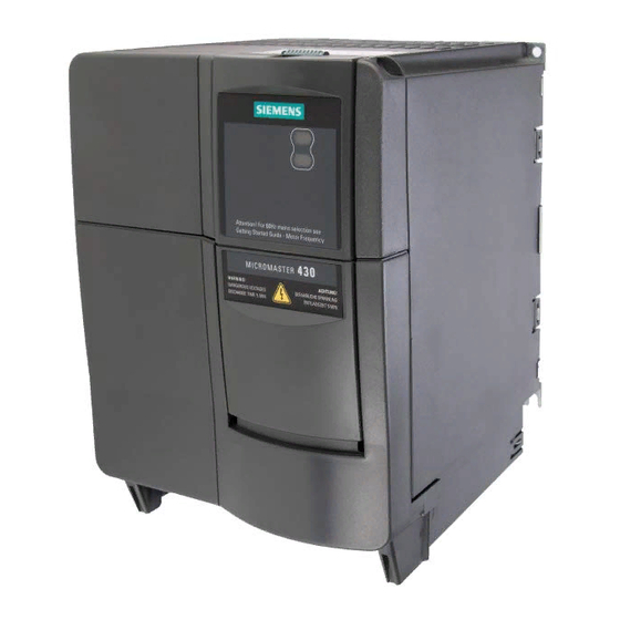
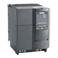
Siemens MICROMASTER 430 Operating Instructions Manual (119 pages)
3AC-frequency inverter
Brand:
Siemens
| Category:
DC Drives
| Size: 7.18 MB
Table of Contents
Issue
7
Issue
11
Table of Contents
12
1 Overview
16
The MICROMASTER 430
17
Features
18
2 Installation
20
Installation after a Period of Storage
22
Figure 2-1 Forming
22
Ambient Operating Conditions
23
Figure 2-2 Ambient Operating Temperature
23
Figure 2-3 Installation Altitude
23
Electro-Magnetic
24
Mechanical Installation
25
Figure 2-4 Drill Pattern for MICROMASTER 430 Frame Sizes C to F
26
Figure 2-5 Installation Dimensions for MICROMASTER 430 Frame Size FX
27
Figure 2-6 Installation Dimensions for MICROMASTER 430 Frame Size GX
28
Table 2-1 Dimensions and Torques of MICROMASTER 430
29
Figure 2-7 Installation of Options for the Electronic Box
30
Electrical Installation
31
Figure 2-8 MICROMASTER 430 Connection Terminals, Frame Sizes C to F
34
Figure 2-9 MICROMASTER 430 Connection Drawing - Frame Size FX
35
Figure 2-10 MICROMASTER 430 Connection Drawing - Frame Size GX
36
Figure 2-11 Motor and Power Connections
37
Figure 2-12 Adaptation of Fan Voltage
38
Figure 2-13 Control Terminals of MICROMASTER 430
39
Figure 2-14 Wiring Guidelines to Minimize the Effects of EMI
41
3 Commissioning
44
Block Diagram
46
Figure 3-1 Inverter Block Diagram
46
Figure 3-2 Configuration of the Analogue Input as a Digital Input
47
Commission Modes
48
Figure 3-3 Panels Available for the MICROMASTER 430 Inverter
48
Figure 3-4 DIP Switch
48
Figure 3-5 Recommended Wiring for the Factory Setting
50
Figure 3-6 Buttons on the BOP-2
53
Figure 3-7 Changing Parameters Via the BOP-2
54
Figure 3-8 Typical Motor Rating Plate Example
58
General Operation
59
Figure 3-9 Thermal Overload Protection
60
4 MICROMASTER 430 Functions
62
Frequency Set Point (P1000)
64
Command Sources (P0700)
64
OFF and Brake Function
65
Control Modes (P1300)
66
MICROMASTER 430 Operating Modes
67
Figure 4-1 Bypass Circuit
67
Figure 4-2 Belt Failure Detection
68
Figure 4-3 Motor Staging
69
Figure 4-4 Energy Saving Mode
70
Free Function Blocks (P2800 Ff)
71
Faults and Alarms
71
5 System Parameters
72
Introduction to MICROMASTER System Parameters
73
Parameter Overview
74
Figure 5-1 Parameter Overview
74
6 Troubleshooting
76
Troubleshooting with the SDP
77
Troubleshooting with the BOP-2
78
Fault Messages
79
Alarm Messages
79
7 MICROMASTER 430 Specifications
80
Table 7-1 MICROMASTER 430 Performance Ratings
81
Table 7-2 Dimensions, Required Cooling Air Flow and Tightening Torques for Power Terminals
82
Table 7-3 Current Reduction Depending on Pulse Frequency
83
8 Options
88
Device-Independent Options
88
Device-Dependent Options
88
9 Electro-Magnetic Compatibility (EMC)
90
Electro-Magnetic Compatibility
91
Appendices
96
A Changing the Operator Panel
96
B Removing Front Covers
97
Removing Front Covers Frame Size C
97
Removing Front Covers Frame Sizes D and E
98
Removing Covers Frame Size F
99
Removing Front Covers Frame Sizes FX and GX
100
C Removing the I/O Board
101
D Removing 'Y' Cap
102
Removing 'Y' Cap Frame Size C
102
Removing 'Y' Cap Frame Sizes D and E
103
Removing 'Y' Cap Frame Sizes F
104
Removing 'Y' Cap Frame Sizes FX
105
Removing 'Y' Cap Frame Sizes GX
106
Applicable Standards
107
F Short Circuit Current Rating (SCCR)
108
List of Abbreviations
109
Index
112
Advertisement
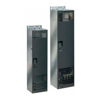
Siemens MICROMASTER 430 Operating Instructions Manual (118 pages)
7.5kW-90kW 3AC-frequency inverters for controlling the speed of three phase AC motors
Brand:
Siemens
| Category:
Inverter
| Size: 2.74 MB
Table of Contents
Safety Instructions
7
Table of Contents
11
1 Overview
15
The MICROMASTER 430
16
Features
17
2 Installation
19
Installation after a Period of Storage
21
Ambient Operating Conditions
21
Figure 2-1 Forming
21
Figure 2-2 Ambient Operating Temperature
21
Figure 2-3 Installation Altitude
22
Mechanical Installation
23
Table 2-1 Dimensions and Torques of MICROMASTER 430
23
Figure 2-4 Drill Pattern for MICROMASTER 430
24
Electrical Installation
25
Figure 2-5 MICROMASTER 430 Connection Terminals
27
Figure 2-6 Motor and Power Connections
28
Figure 2-7 Wiring Guidelines to Minimize the Effects of EMI
30
3 Commissioning
31
Block Diagram
33
Figure 3-1 Inverter Block Diagram
33
Figure 3-2 Configuration of the Analogue Input as a Digital Input
34
Analogue Inputs
34
Commission Modes
35
Figure 3-2 Panels Available for the MICROMASTER 430 Inverter
35
Figure 3-3 DIP Switch
35
Table 3-1 Default Settings for Operation Using the SDP
36
Figure 3-5 Basic Operation with SDP
37
Table 3-2 Default Settings for Operation Using the BOP-2
39
Figure 3-5 Buttons on the BOP-2
40
Figure 3-6 Changing Parameters Via the BOP-2
41
Access Level
43
Figure 3-7 Typical Motor Rating Plate Example
45
General Operation
46
4 MICROMASTER 430 Functions
49
Frequency Set Point (P1000)
50
Command Sources (P0700)
51
OFF and Brake Function
51
Compound Braking
52
Control Modes (P1300)
53
MICROMASTER 430 Operating Modes
54
Figure 4-1 Bypass Circuit
54
Micromaster 430
54
Figure 4-2 Belt Failure Detection
55
Figure 4-3 Motor Staging
56
Figure 4-4 Energy Saving Mode
57
Faults and Alarms
58
5 System Parameters
59
Introduction to MICROMASTER System Parameters
60
Parameter Overview
61
Figure 5-1 Parameter Overview
61
Parameter List (Short Form)
62
Command and Drive Datasets - Overview
75
6 Troubleshooting
79
Troubleshooting with the SDP
80
Table 6-1 Inverter Conditions Indicated by the Leds on the SDP
80
Troubleshooting with the BOP-2
81
Fault Messages
82
Alarm Messages
86
7 MICROMASTER 430 Specifications
91
Table 7-1 MICROMASTER 430 Performance Ratings
92
Table 7-2 Tightening Torques for Power Terminals
93
Table 7-3 MICROMASTER 430 Specifications
93
8 Options
97
Device-Independent Options
97
Device-Dependent Options
97
9 Electro-Magnetic Compatibility (EMC)
99
Electro-Magnetic Compatibility
100
Figure 3-9
101
Table 9-1 General Industrial (Unfiltered Inverters Together with Approved External Mains Filter)
101
Table 9-2 Filtered Industrial
101
Table 9-3 Filtered for Residential, Commercial and Light Industry
102
Table 9-4 Compliance Table
102
Appendices
103
A Changing the Operator Panel
103
B Removing Covers Frame Size C
104
C Removing Covers Frame Sizes D and E
105
D Removing Covers Frame Size F
106
E Removing the I/O Board
107
F Removing 'Y' Cap Frame Size C
108
G Removing 'Y' Cap Frame Sizes D and E
109
H Removing 'Y' Cap Frame Sizes F
110
I Applicable Standards
111
List of Abbreviations
112
Index
113
Siemens MICROMASTER 430 Manual (110 pages)
Brand:
Siemens
| Category:
Inverter
| Size: 7.55 MB
Table of Contents
Micromaster 430
8
Table of Contents
12
1 Overview
16
The MICROMASTER 430
17
Features
18
2 Installation
20
General
22
Ambient Operating Conditions
22
Figure 2-1 Forming
22
Figure 2-2 Ambient Operating Temperature
22
Figure 2-3 Installation Altitude
23
Mechanical Installation
24
Table 2-1 Dimensions and Torques of MICROMASTER 430
24
Figure 2-4 Drill Pattern for MICROMASTER 430
25
Electrical Installation
26
Figure 2-5 MICROMASTER 430 Connection Terminals
28
Figure 2-6 Motor and Power Connections
29
Figure 2-7 Wiring Guidelines to Minimize the Effects of EMI
31
3 Commissioning
32
Block Diagram
34
Figure 3-1 Inverter Block Diagram
34
Commission Modes
35
Figure 3-2 Panels Available for the MICROMASTER 430 Inverter
35
Figure 3-3 DIP Switch
35
Table 3-1 Default Settings for Operation Using the SDP
36
Figure 3-4 Basic Operation with SDP
37
Table 3-2 Default Settings for Operation Using the BOP-2
39
Figure 3-5 Buttons on the BOP-2
40
Figure 3-6 Changing Parameters Via the BOP-2
41
Figure 3-7 Typical Motor Rating Plate Example
45
General Operation
46
4 MICROMASTER 430 Functions
48
Frequency Set Point (P1000)
49
Command Sources (P0700)
50
OFF and Brake Function
50
Compound Braking
51
Control Modes (P1300)
52
MICROMASTER 430 Operating Modes
53
Figure 4-1 Bypass Circuit
53
Micromaster 430
53
Figure 4-2 Belt Failure Detection
54
Figure 4-3 Motor Staging
55
Figure 4-4 Energy Saving Mode
56
Faults and Alarms
57
5 System Parameters
58
Introduction to MICROMASTER System Parameters
59
Parameter Overview
60
Figure 5-1 Parameter Overview
60
Parameter List (Short Form)
61
6 Troubleshooting
74
Troubleshooting with the SDP
75
Table 6-1 Inverter Conditions Indicated by the Leds on the SDP
75
Troubleshooting with the BOP-2
76
Fault Messages
77
Alarm Messages
81
7 MICROMASTER 430 Specifications
86
Table 7-1 MICROMASTER 430 Performance Ratings
87
Table 7-2 Tightening Torques for Power Terminals
88
Table 7-3 MICROMASTER 430 Specifications
88
8 Options
92
Device-Independent Options
92
Device-Dependent Options
92
9 Electro-Magnetic Compatibility (EMC)
94
Electro-Magnetic Compatibility
95
Table 9-1 General Industrial (Unfiltered Inverters Together with Approved External Mains Filter)
96
Table 9-2 Filtered Industrial
96
Table 9-3 Filtered for Residential, Commercial and Light Industry
97
Table 9-4 Compliance Table
97
Appendices
98
A Changing the Operator Panel
98
B Removing Covers Frame Size C
99
C Removing Covers Frame Sizes D and E
100
D Removing Covers Frame Size F
101
E Removing the I/O Board
102
F Removing 'Y' Cap Frame Size C
103
G Removing 'Y' Cap Frame Sizes D and E
104
H Removing 'Y' Cap Frame Sizes F
105
I Applicable Standards
106
List of Abbreviations
107
Index
108
Micromaster
109
Advertisement
Siemens MICROMASTER 430 Operating Instructions Manual (132 pages)
CANopen Option Module
Brand:
Siemens
| Category:
Control Unit
| Size: 0.94 MB
Table of Contents
Data Transfer Using Canopen
3
Intended Use
6
Table of Contents
7
1 Description
9
2 General Can/Canopen Definitions
11
CAN (Controller-Area-Network)
11
Canopen
13
General Information
14
3 Data Transfer Using Canopen
17
MICROMASTER Object Directory
17
Canopen Communication Services
31
NMT (Network Management) Services
31
Communication Monitoring Services
34
Boot up Telegram
36
SDO (Service Data Object) Services
37
PDO (Process Data Object) Services
45
Synchronization Service
49
EMERGENCY Object Service
50
Controlling MICROMASTER Drive Converters Via Canopen
55
Canopen Control Word
56
Canopen Status Word
57
MICROMASTER Control and Status Word 2
60
Modes of Operation and Modes of Operation Display
62
4 Connecting to Canopen
65
Installing the Canopen Module for Sizes A, B, C
65
Installing the Canopen Module for Sizes D, E, F
67
Installing the Canopen Module for Sizes FX, GX
69
Bus Connection
70
5 Commissioning with Canopen
73
Electronic Data Sheet (EDS)
73
Important Parameters When Commissioning the System for the First Time
74
Parameter "P2040" (Object 0X27F8*), Telegram Failure Time
75
Setting-Up the Pdos
76
Timing of the Pdos
79
PDO Properties in Parameter "P2041
79
First Commissioning in the Velocity Mode
89
Additional Commissioning Via Canopen
89
Additional Helpful Commands for the Velocity Mode
95
First Commissioning in the Profile Torque Mode
96
Additional Commissioning Via Canopen
96
Additional Helpful Commands for the Profile Torque Mode
102
6 Commissioning Using a Commissioning (Start-Up) Tool
103
Assigning Process Data
103
Parameter "P0927" - Change Source for Parameters
106
Parameter Settings for the Modes
107
Velocity Mode
107
Profile Torque Mode
110
7 Diagnostics and Troubleshooting
113
LED Display
113
Alarms (Warnings and Faults)
115
Diagnostic Parameters
119
Software Release and Information
121
8 Attachment
123
Technical Data
123
EMC Information
124
List of Abbriviations
125
Siemens MICROMASTER 430 Getting Started Manual (44 pages)
frequency inverter
Brand:
Siemens
| Category:
Inverter
| Size: 4.21 MB
Siemens MICROMASTER 430 Getting Started Manual (32 pages)
Brand:
Siemens
| Category:
Touch terminals
| Size: 5.65 MB
Siemens MICROMASTER 430 Maintenance Instruction (3 pages)
Powerblock 110,0/132,0 kW
Brand:
Siemens
| Category:
Industrial Electrical
| Size: 0.43 MB
Siemens MICROMASTER 430 Maintenance Instruction (2 pages)
Fan Transformer 110,0/132,0 kW, 210 A/260 A
Brand:
Siemens
| Category:
Transformer
| Size: 0.34 MB
Siemens MICROMASTER 430 Maintenance Instruction (2 pages)
Fan Transformer
Brand:
Siemens
| Category:
Transformer
| Size: 0.31 MB
Advertisement
Related Products
Siemens MICROMASTER 411
Siemens MICROMASTER 420
Siemens MICROMASTER 440 Series
Siemens Micromaster Eco
Siemens micromaster 410
Siemens MICROMASTER Vector Series
Siemens MICROMASTER Vector MMV25
Siemens MICROMASTER Vector MMV12
Siemens MICROMASTER Vector MMV55
Siemens MICROMASTER Vector MMV75
Siemens Categories
Industrial Equipment
Controller
Oven
Control Unit
Washer
More Siemens Manuals
Login
Sign In
OR
Sign in with Facebook
Sign in with Google
Upload manual
Upload from disk
Upload from URL