Sign In
Upload
Manuals
Brands
Siemens Manuals
Controller
HydroRanger 200 HMI
Siemens HydroRanger 200 HMI Manuals
Manuals and User Guides for Siemens HydroRanger 200 HMI. We have
2
Siemens HydroRanger 200 HMI manuals available for free PDF download: Operating Instructions Manual
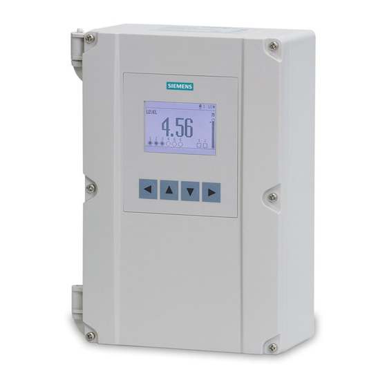
Siemens HydroRanger 200 HMI Operating Instructions Manual (404 pages)
SITRANS Ultrasonic Controllers
Brand:
Siemens
| Category:
Controller
| Size: 6.98 MB
Table of Contents
Table of Contents
5
Introduction
17
Purpose of this Documentation
17
Checking the Consignment
17
Security Information
17
Transportation and Storage
18
Notes on Warranty
18
Safety Notes
21
Description
25
Overview
25
Features
26
Applications
26
Approvals
27
Modbus Communication
27
Installing/Mounting
29
Basic Safety Notes
29
Mounting Instructions
31
Mounting Locations
31
Mounting on Wall
31
Cable Routed through a Conduit
34
Cable Exposed and Entering through the Cable Glands
35
Panel Mount
36
Cutout Instructions
37
Panel Mount Dimensions
37
Mounting the Enclosure
37
Wiring Compartment
38
Wiring Compartment
39
Installing the Smartlinx Communication Card
40
Connecting
41
Basic Safety Notes
41
Connecting Diagram
42
Terminal Board
43
Cables
43
Transducers
44
Relays
45
Temperature Sensor
46
Ma Input
46
Ma Output
47
Level System Synchronization
47
Power
48
Digital Communication
48
RS-232 Serial Connection
49
Discrete Inputs
50
Commissioning
51
Local Commissioning
51
Activating the Device
52
RUN Mode
52
The Local Display
53
Display Field Descriptions
55
Auxiliary Reading
56
Multiple Readings
56
PROGRAM Mode
57
Key Functions in Measurement Mode
57
Programming the Device
57
Parameter Menus
58
Key Functions in Edit Mode
61
Quick Start Wizards
61
Setting Wizards Via Graphical Display
62
Wizards (1.)
63
Quick Start (1.1.)
63
Requesting an Echo Profile
88
Application Examples
89
Level Application
90
Flow Application
91
Operating
93
Single-Point Models
93
Average or Differential
94
Dual-Point Models
94
Average or Differential
95
Measurement Conditions
96
Relays
97
General Introduction
97
Relay Functions
98
Alarm
98
Pump
99
Totalizing and Sampling
99
Relay Status - Navigation Pane
99
Relay-Related Parameters
100
Relay Activation
101
Preset Applications
102
Relay Fail-Safe
106
Security
106
Parameter Types
106
Display Readout
106
Adjusting the Primary Reading
107
Backup Level Override
107
Backup Level Override Parameters
108
Discrete Inputs
108
Wiring the Discrete Inputs
109
Adjusting the Discrete Input Logic
109
Ma I/0
109
Ma Input
109
Ma Output
110
Volume
111
Readings
111
Vessel Shape and Dimensions
112
Characterization Chart
113
Alarms
115
Level
115
Setting Simple Level Alarms
116
Rate
116
In-Bounds/Out-Of-Bounds Range
117
Cable Fault
117
Temperature
118
Loss of Echo (LOE)
118
Pump Control
119
Setting a Pump down Group
119
Set Relays to Alternate Duty Assist
120
Set the on Setpoints
120
Set the off Setpoints
120
Setting a Pump up (Reservoir) Group
121
Set Relays to Alternate Duty Assist
122
Set the Relay on Setpoints
122
Set the Relay off Setpoints
122
Other Pump Control Algorithms
123
Set Relays to Alternate Duty Backup
123
Set Relays to Fixed Duty Assist
123
Set Relays to Fixed Duty Backup
124
Set Relays to Service Ratio Duty Assist
125
Set Relays to First in First out
126
Optional Pump Controls
127
Starting Pumps by Rate of Level Change
127
Rotating Pumps by Service Ratio
128
Totalizing Pumped Volume
129
Setting Independent Fail-Safe Controls
130
Setting a Pump to Run-ON
130
Setting the Pump Start Delays
131
Reducing Wall Cling
131
Grouping Pumps
132
Setting a Flush Valve
132
Relay Controlled by Communications
133
Tracking Pump Usage
133
Rake (Screen) Control
133
Setting a Rake Control
134
Setting Common Parameters
135
Set Relay 1 (Operate Rake)
135
Set Relays 2 to 4 (Level Alarms)
136
External Totalizers and Flow Samplers
136
Relay Contacts
137
Totalizer
137
Flow Sampler
138
Based on Volume and Time
138
Open Channel Monitoring (OCM)
139
Common Parameters
140
Setting Zero Head
141
Setting Totalized Volume
142
Applications Supported by the Device
143
BS-3680/ISO 1438/1 Thin Plate V-Notch Weir
143
BS-3680/ISO 4359 Rectangular Flume
144
Palmer-Bowlus Flume
145
H-Flume
146
Pmds with Exponential Flow to Head Function
147
Parshall Flume
150
Leopold-Lagco Flume
151
Cut Throat Flume
152
Universal Calculation Support
153
Typical Flow Characterization
153
Example Flumes
154
Example Weir Profiles
155
Configuration Testing
155
I/0 Checkout
155
Application Test
156
Parameter Reference
157
Key Terms
157
Parameter Indexing
158
Index Selector Examples
160
Sensor and Measurement
160
Calibration
161
Pumps
161
High Level Alarm
162
Index Types
163
Quick Start Wizards
164
Setup (2.)
164
Sensor (2.1.)
164
Units (2.1.1.)
164
Level Selector (2.1.2.)
164
Sensor Mode (2.1.3.)
165
Transducer Selector (2.1.4.)
166
Transducer (2.1.5.)
166
Material (2.1.6.)
167
Short Shot Frequency (2.1.7.)
167
Long Shot Frequency (2.1.8.)
167
Short Shot Duration (2.1.9.)
168
Long Shot Duration (2.1.10.)
168
Number of Short Shots (2.1.11.)
168
Number of Long Shots (2.1.12.)
169
Shot Synchro (2.1.13.)
169
Scan Delay (2.1.14.)
169
Scan Time (2.1.15.)
170
Shot Delay (2.1.16.)
170
Shot/Pulse Mode (2.1.17.)
170
Calibration (2.2.)
171
Level Selector (2.2.1)
171
Span (2.2.2.)
171
Transducer Selector (2.2.3.)
171
Empty (2.2.4.)
172
Sensor Offset (2.2.5.)
173
Blanking (2.2.6.)
173
Range Extension (2.2.7.)
174
Rate (2.3.)
174
Transducer Selector (2.3.1.)
174
Fill Rate/Minute (2.3.2.)
175
Empty Rate/Minute (2.3.3.)
175
Response Rate (2.3.4.)
176
Rate Filter (2.3.5.)
177
Rate Filter Time (2.3.6.)
177
Rate Filter Distance (2.3.7.)
177
Level Selector (2.2.8)
178
Filling Indicator (2.3.9.)
178
Emptying Indicator (2.3.10.)
178
Fail-Safe (2.4.)
179
Transducer Selector (2.4.1.)
179
LOE Timer (2.4.2.)
179
Level Selector (2.4.3.)
180
Fail-Safe Mode (2.4.4.)
180
Material Level (2.4.5.)
180
Fail-Safe Advance (2.4.6.)
181
Ma Output Selector (2.4.7.)
181
Ma Fail-Safe Mode (2.4.8.)
181
Ma Fail-Safe Value (2.4.9.)
182
Current Output (2.5.)
182
Ma Output Selector (2.5.1.)
182
Ma Output Range (2.5.2.)
182
Current Output Function (2.5.3.)
183
Ma Output Allocation (2.5.4.)
183
Ma Setpoint (2.5.5.)
184
Ma Setpoint (2.5.6.)
184
Minimum Ma Limit (2.5.7.)
184
Maximum Ma Limit (2.5.8.)
184
Milliamp Output (2.5.9.)
184
Fail-Safe Mode (2.5.10.)
185
Ma Output Trim (2.5.11.)
185
Ma Output Trim (2.5.12.)
185
Current Input (2.6.)
186
Ma Input Range (2.6.1.)
186
0/4 Ma Level Value (2.6.2.)
186
Ma Level Value (2.6.3.)
186
Ma Damp Filter (2.6.4.)
187
Scaled Ma Input Value (2.6.5.)
187
Raw Ma Input Value (2.6.6.)
187
Volume (2.7.)
187
Level Selector (2.7.1.)
187
Vessel Shape (2.7.2.)
188
Maximum Volume (2.7.3.)
190
Dimension a (2.7.4.)
190
Dimension L (2.7.5.)
191
Transducer Selector (2.7.6.)
191
Inflow/Discharge Adjust (2.7.7.)
191
Table 1-8 (2.7.8.)
192
Table 9-16 (2.7.9.)
193
Table 17-24 (2.7.10.)
194
Relays (2.8.)
195
Table 25- 32 ( 2.7.11.)
195
Basic Setup (2.8.1.)
195
Modifiers (2.8.2.)
202
Discrete Inputs (2.9.)
209
Backup Level Override (2.9.1.)
209
Discrete Input Logic (2.9.2.)
211
Other Control (2.10.)
212
External Totalizer (2.10.1.)
212
Transducer Selector (2.10.1.1.)
212
Multiplier (2.10.1.2.)
213
Relay Duration (2.10.1.3.)
213
External Sampler (2.10.2.)
214
Signal Processing (2.11.)
220
Temperature and Velocity (2.11.1.)
220
Echo Select (2.11.2.)
224
TVT Setup (2.11.3.)
229
TVT Shaper (2.11.4.)
233
Measurement Verification (2.11.5.)
235
Display (2.12.)
238
Local Display Backlight (2.12.1)
238
LCD Contrast (2.12.2.)
238
Level Selector (2.12.3.)
239
Decimal Position (2.12.4.)
239
Convert Reading (2.12.5.)
240
Offset Reading (2.12.6.)
240
Default Auxiliary Reading (2.12.7.)
241
Display Delay (2.12.8.)
241
Flow (2.13.)
241
Transducer Selector (2.13.1.)
241
Primary Measuring Device (2.13.2.)
242
Auto Zero Head (2.13.3.)
242
Basic Setup (2.13.4.)
243
PMD Dimensions (2.13.5.)
248
Universal Head Vs Flow (2.13.6.)
249
Totalizers (2.14.)
252
Transducer Selector (2.14.1.)
252
Running Totalizers (2.14.)
252
Running Totalizers High (2.14.2.)
252
Running Totalizers Low (2.14.3.)
253
Totalizer Decimal Position (2.14.4.)
253
Totalizer Multiplier (2.14.5.)
254
Maintenance and Diagnostics (3.)
254
Identification (3.1.)
254
Tag (3.1.1.)
254
Descriptor (3.1.2.)
254
Message (3.1.3.)
254
Order Number (3.1.4.)
255
Serial Number (3.1.5.)
255
Hardware Revision (3.1.6.)
255
Firmware Revision (3.1.7.)
255
Loader Revision (3.1.8.)
255
Manufacture Date (3.1.9.)
255
Date Last Configured (3.1.10.)
255
Diagnostics (3.2.)
255
Transducer Selector (3.2.1.)
255
Echo Profile (3.2.2.)
256
Master Reset (3.2.3.)
256
Power-ON Resets (3.2.4.)
257
Power-ON Time (3.2.5.)
257
Relay Selector (3.2.6.)
257
Relay Logic Test (3.2.7.)
257
Measurement Values (3.2.8.)
257
Pump Records (3.2.9.)
262
Temperature Peak Values (3.2.10)
263
Echo Quality (3.2.11.)
264
Smartlinx Diagnostics (3.2.12.)
265
Simulation (3.3.)
268
Discrete Inputs
268
Communication (4.)
269
Communications Port Selector (4.1.)
269
Device Address (4.2.)
269
Communications Timeout (4.3.)
270
Protocol (4.4.)
270
Serial Baud Rate (4.5.)
270
Parity (4.6.)
271
Data Bits (4.7.)
271
Stop Bits (4.8.)
271
Modem Available (4.9.)
271
Modem Inactivity Timeout (4.10.)
272
Parameter Index Location (4.11.)
272
Smartlinx Reserved Parameters (4.12.1. to 4.12.5.)
273
Security (5.)
273
Write Protection (5.1.)
273
User PIN (5.2.)
273
Protocol Selector (5.3.)
274
Communications Control (5.4.)
274
Language (6.)
275
Service and Maintenance
277
Firmware Updates
277
Basic Safety Notes
278
Cleaning
280
Cleaning the Enclosure
280
Maintenance and Repair Work
280
Return Procedure
281
Transport
281
Disposal
282
Diagnosing and Troubleshooting
283
Communication Troubleshooting
283
General Fault Codes
284
Common Problems Chart
285
Noise Problems
288
Determining the Noise Source
289
Non-Transducer Noise Sources
289
Avoiding Common Wiring Problems
290
Reducing Electrical Noise
290
Reducing Acoustical Noise
290
Measurement Difficulties
291
Loss of Echo (LOE)
291
Adjust Transducer Aiming
291
Increase Fail-Safe Timer Value
291
Install a Transducer with a Narrower Beam
292
Fixed Reading
292
Obstructions in the Sound Beam
292
Nozzle Mountings
292
Set the Device to Ignore the Bad Echo
293
Wrong Reading
293
Transducer Ringing
294
Unit Repair and Excluded Liability
295
Technical Data
297
Power
297
Operating Conditions
298
Performance
298
Programming
299
Outputs
299
Inputs
300
Construction
301
Approvals
302
Transducers
302
Technical Reference
303
Transmit Pulse
303
A.1 Transmit Pulse
303
Echo Processing
304
TVT (Time Varying Threshold) Curves
304
A.2 Echo Processing
304
Auto False Echo Suppression
305
Algorithm
306
A.5 Algorithm
306
Distance Calculation
307
A.6 Distance Calculation
307
Sound Velocity
308
A.7 Sound Velocity
308
Scanning
309
Volume Calculation
309
A.8 Scanning
309
Flow Calculation
310
A.10 Flow Calculation
310
Response Rate
313
Analog Output
313
A.11 Response Rate
313
Current Output Function
314
Loss of Echo (LOE)
314
Fail-Safe Mode
314
Pump Control Reference
315
Pump Control Options
315
Pump Groups
315
Pump by Rate
315
Pump Control Algorithms
315
Fixed Duty Assist
316
Fixed Duty Backup
316
Alternate Duty Assist
318
Alternate Duty Backup
319
Service Ratio Duty Assist
320
Service Ratio Duty Backup
320
First in First out
320
Pump by Rate
321
Other Pump Controls
321
B.12 Pump by Rate
321
Communications
323
Device Communication Systems
323
Modbus
323
Optional Smartlinx Cards
323
C.1 Device Communication Systems
323
Communication Systems
324
Communication Ports
324
C.4 Communication Systems
324
Modbus
325
Smartlinx
325
C.6 Modbus
325
Communications Installation
326
Wiring Guidelines
326
C.8 Communications Installation
326
Configuring Communications Ports (Parameters)
328
SIMATIC Process Device Manager (PDM)
329
Device Description
329
Modbus Register Map
330
Word Order (R40,062)
331
Map ID (R40,063)
331
Product ID (R40,064)
332
Point Data (R41,010 - R41,031)
332
Totalizer (R41,040 - R41,043)
332
C.13 Product ID (R40,064)
332
Input/Output (R41,070 - R41,143)
333
Discrete Inputs (R41,070)
333
Relay Outputs (R41,080)
333
Ma Input (R41,090)
333
Ma Outputs (R41,110-41,111)
333
C.16 Input/Output (R41,070 – R41,143)
333
Pump Control (R41,400-R41,474)
334
Pump on Setpoint (R41,420-R41,425)
334
Pump off Setpoint (R41,430-R41,435)
334
Pumped Volume (R41,440-R41,443)
334
Pump Hours (R41,450-R41,461)
334
C.21 Pump Control (R41,400-R41,474)
334
Pump Starts (R41,470-R41,475)
335
Parameter Access (R43,998-R46,999)
335
Parameter Indexing
336
Reading Parameters
336
C.28 Parameter Indexing
336
Global Index Method
337
Parameter-Specific Index Method
338
Writing Parameters
338
Global Index Method
338
Parameter-Specific Index Method
339
Format Words
339
Global Index Method
339
Format Registers
340
C.31.3 Format Registers
340
Data Types
341
Numeric Values
341
Bit Values
341
C.32 Data Types
341
Unsigned Double Precision Integer (UINT32)
342
Split Values
343
C.36 Split Values
343
Text Messages
344
C.37 Text Messages
344
Relay Function Codes (2.8.1.4. Relay Function Only)
345
Error Handling
346
Modbus Responses
346
C.39 Error Handling
346
Error Handling
347
Communication Troubleshooting
348
General
348
Specific
348
C.40 Communication Troubleshooting
348
Single Parameter Access (SPA)
349
Mapping
349
Reading Parameters
349
Writing Parameters
350
Format Register
350
C.41.3 Writing Parameters
350
Error Codes
351
C.41.5 Error Codes
351
Updating Software
353
Upgrading
355
Mounting a Device
355
Connecting the Transducer
355
Co-Axial Transducer Extension
356
Connecting a Transducer with RG62 Co-Axial Extension Cable
356
Device Installation (for Retrofitting Older Installations)
357
Conduit Entry for Class I, DIV 2 Applications
359
G.1 Programming Chart
363
Programming Chart
363
LCD Menu Structure
373
Certificates and Support
391
Technical Support
391
QR Code Label
391
I.1 Technical Support
391
Certificates
392
I.3 Certificates
392
Index
393
Advertisement
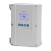
Siemens HydroRanger 200 HMI Operating Instructions Manual (318 pages)
Ultrasonic Controllers
Brand:
Siemens
| Category:
Controller
| Size: 4.53 MB
Table of Contents
Table of Contents
3
Introduction
11
The Manual
11
Manual Symbols
11
Application Examples
12
Firmware Revision History
12
Sensor Node
12
Hmi
12
Safety Notes
13
Safety Marking Symbols
13
FCC Conformity
14
CE Electromagnetic Compatibility (EMC) Conformity
14
Description
17
Overview
17
Features
17
Applications
18
Approvals and Certificates
18
Installing and Mounting
19
Mounting Locations
20
Mounting Instructions
21
Wall Mount
21
Cable Routed through a Conduit
22
Cable Exposed and Entering through the Cable Glands
23
Panel Mount
24
Mounting the Enclosure
25
Hydroranger 200 HMI Wiring Compartment
26
Replacing the Battery
27
Installing the Smartlinx®Communications Card
28
Connecting
29
Terminal Board
30
Cables
31
Transducers
31
Relays
32
Temperature Sensor
32
Ma Input
33
Ma Output
33
Level System Synchronization
33
Power
34
Digital Communications
34
RS-232 Serial Connection
35
Discrete Inputs
35
Commissioning
37
Local Commissioning
37
Activating the Hydroranger 200 HMI
37
RUN Mode
37
Measurement Views in RUN Mode
38
The LCD Display
38
Measurement Mode Display: Normal Operation
38
Auxiliary Reading
39
Multiple Readings
40
PROGRAM Mode
41
Key Functions in Measurement Mode
41
Programming the Hydroranger 200 HMI
41
Parameter Menus
41
Quick Start Wizards
45
Setting Wizards Via Graphical Display
45
Application Examples
68
Level Application
68
Flow Application
69
General Operation
71
Single-Point Models
72
Average or Differential
72
Dual-Point Models
73
Average or Differential
73
Measurement Conditions
73
Response Rate
74
Dimensions
74
Fail-Safe Indexes
74
Relays
75
General Introduction
75
Relay Functions
75
Alarm
75
Pump
76
Totalizing and Sampling
76
Relay Status - Navigation View
77
Relay-Related Parameters
77
Relay Wiring Test
78
Relay Activation
78
Preset Applications
79
Relay Fail-Safe
80
Security
80
Parameter Types
80
Display Readout
81
Adjusting the Primary Reading
81
Backup Level Override
82
Backup Level Override Parameters
82
Discrete Inputs
83
Wiring the Discrete Inputs
83
Adjusting the Discrete Input Logic
83
Ma I/O
84
Ma Input
84
Ma Output
84
Volume
86
Readings
86
Vessel Shape and Dimensions
86
Characterization Chart
87
Alarms
89
Level
89
Setting Simple Level Alarms
90
Rate
90
In-Bounds/Out-Of-Bounds Range
90
Cable Fault
91
Temperature
91
Loss of Echo (LOE)
92
Pump Control
93
Setting a Pump down Group
93
Setting a Pump up (Reservoir) Group
94
Other Pump Control Algorithms
96
Set Relays to Alternate Duty Backup
96
Set Relays to Fixed Duty Assist
96
Set Relays to Fixed Duty Backup
97
Set Relays to Service Ratio Duty Assist
97
Set Relays to First in First out
98
Optional Pump Controls
99
Starting Pumps by Rate of Level Change
99
Rotating Pumps by Service Ratio
100
Totalizing Pumped Volume
101
Setting Independent Fail-Safe Controls
102
Setting a Pump to Run-ON
102
Setting the Pump Start Delays
103
Reducing Wall Cling
103
Grouping Pumps
104
Setting a Flush Valve
104
Relay Controlled by Communications
105
Tracking Pump Usage
105
Rake (Screen) Control
106
Setting a Rake Control
106
Setting Common Parameters
107
Set Relay 1 (Operate Rake)
107
Set Relays 2 to 4 (Level Alarms)
107
External Totalizers and Flow Samplers
108
Relay Contacts
108
Totalizer
108
Flow Sampler
109
Based on Volume and Time
109
Open Channel Monitoring (OCM)
110
Common Parameters
110
Setting Zero Head
111
Setting Totalized Volume
113
Applications Supported by Hydroranger 200 HMI
113
BS-3680 / ISO 1438/1 Thin Plate V-Notch Weir
113
BS-3680 / ISO 4359 Rectangular Flume
114
Palmer-Bowlus Flume
115
H-Flume
116
Pmds with Exponential Flow to Head Function
117
Applicable Weir Profiles
117
Non-Applicable Weir Profiles
118
Parshall Flume
119
Leopold Lagco Flume
120
Cut Throat Flume
121
Universal Calculation Support
122
Typical Flow Characterization
122
Example Flumes
123
Example Weirs
123
Configuration Testing
125
I/O Checkout
125
Application Test
125
Parameters
127
Key Terms
127
Parameter Indexing
128
Index Selector Examples
129
Sensor and Measurement
129
Calibration
130
Pumps
130
High Level Alarm
130
Index Types
131
Alphabetical List
216
Service and Maintenance
225
Firmware Updates
225
Decontamination Declaration
225
Troubleshooting
227
Communication Troubleshooting
227
General Fault Codes
228
Common Problems Chart
229
Noise Problems
236
Determine the Noise Source
236
Avoiding Common Wiring Problems
237
Non-Transducer Noise Sources
237
Reducing Acoustical Noise
237
Reducing Electrical Noise
237
Measurement Difficulties
238
Adjust Transducer Aiming
238
Increase Fail-Safe Timer Value
238
Install a Transducer with a Narrower Beam
238
Loss of Echo (LOE)
238
Fixed Reading
239
Wrong Reading
240
Unit Repair and Excluded Liability
241
Technical Data
243
Appendix A: Technical Reference
249
TVT (Time Varying Threshold) Curves
250
Algorithm
251
Sound Velocity
252
Scanning
253
Universal Curved
254
Universal Linear
255
Response Rate
256
Loss of Echo (LOE)
257
Appendix B: Pump Control Reference
258
Fixed Duty Assist
259
Alternate Duty Assist
260
Service Ratio Duty Assist
261
Service Ratio Duty Backup
262
Appendix C: Communications
263
Communication Ports
264
Communications Installation
265
Configuring Communications Ports (Parameters)
267
SIMATIC Process Device Manager (PDM)
268
Modbus Register Map
269
Parameter Indexing
274
Parameter-Specific Index Method
275
Global Index Method
276
Data Types
278
Split Values
279
Text Messages
280
Error Handling
282
Communication Troubleshooting
283
Single Parameter Access (SPA)
284
Writing Parameters
285
Error Codes
286
Appendix D: Updating Software
287
Appendix E: Upgrading
288
Connecting a Transducer with RG62 Co-Axial Extension Cable
289
Appendix F: Conduit Entry for Class I, DIV 2 Applications
290
Programming Chart
293
LCD Menu Structure
302
Index
309
Advertisement
Related Products
Siemens ERTEC 200P-2
Siemens ERTEC 200P
Siemens BACNET 2584
Siemens BACNET 2590
Siemens Albatros 2 RVS13 Series
Siemens Albatros 2 QAA75 Series
Siemens Albatros 2 QAA78 Series
Siemens Albatros 2 QAA55 Series
Siemens LOGO! 24RC
Siemens LOGO! 24RCL
Siemens Categories
Industrial Equipment
Controller
Oven
Control Unit
Washer
More Siemens Manuals
Login
Sign In
OR
Sign in with Facebook
Sign in with Google
Upload manual
Upload from disk
Upload from URL