Sign In
Upload
Manuals
Brands
SIEB & MEYER Manuals
Control Unit
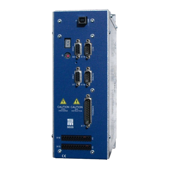
SD2S
User Manuals: SIEB & MEYER SD2S Frequency Converter
Manuals and User Guides for SIEB & MEYER SD2S Frequency Converter. We have
2
SIEB & MEYER SD2S Frequency Converter manuals available for free PDF download: Hardware Description
SIEB & MEYER SD2S Hardware Description (196 pages)
Drive System
Brand:
SIEB & MEYER
| Category:
Control Unit
| Size: 12.64 MB
Table of Contents
Table of Contents
3
1 About this Manual
8
Illustration of Warnings
8
Abbreviations
8
2 General Information
10
3 Safety Instructions
11
Standards and Regulations
11
Working on the Device
11
Appropriate Use
12
Reasonably Foreseeable Misuse
13
Transport and Storage
13
Installation
14
Electrical Connection
15
Operation
16
Maintenance
17
Disposal
17
Legal Warranty
18
4 Unit Assembly Complying EMC
19
Emission of Line and Field Interferences According to Category C3
19
5 Drive Amplifier SD2
21
Block Diagram
21
Type Plate
22
Device Designation
23
Components of the Drive System Sd2X
24
6 Single-Axis Drive Amplifiers
25
Device Variant 0362111Xy (Max. 80 A)
25
Dimensions
26
Technical Data
27
Connectors
28
Device Variant 0362111MF/0362111NF (Max. 200 A)
29
Dimensions
30
Technical Data
31
Connectors
32
Device Variant 0362111OF (Max. 160 A) with Integrated Water-Cooled Heat Sink
33
Dimensions
34
Technical Data
35
Connectors
36
Device Variant 0362111RF (Max. 220 A) with Integrated Water-Cooled Heat Sink
37
Dimensions
38
Technical Data
39
Connectors
40
Device Variant 0362111SF (Max. 358 A) with Integrated Water-Cooled Heat Sink
41
Dimensions
43
Technical Data
44
Connectors
45
Device Variants 0362114Xy (Max. 80 A) with Integrated Heat Sink
46
Dimensions
47
Technical Data
48
Connectors
49
Device Variant 0362114MF/0362114NF (Max. 200 A) with Integrated Heat Sink
50
Dimensions
51
Technical Data
52
Connectors
53
Device Variant 0362114QF (Max. 120 A) with Integrated Heat Sink
54
Dimensions
55
Technical Data
56
Connectors
57
7 Double-Axis Drive Amplifiers
59
Device Variant 0362110Xxy (Max. 40 A)
59
Dimensions
60
Technical Data
61
Connectors
62
Device Variant 0362112Xxy (Max. 120 A)
63
Dimensions
64
Technical Data
65
Connectors
66
Device Variant 0362113Xxy (Max. 40 A) with Integrated Heat Sink
67
Dimensions
68
Technical Data
69
Connectors
70
Device Variant 0362115Xxy (Max. 120 A) with Integrated Heat Sink
71
Dimensions
72
Technical Data
73
Connectors
74
8 Compact Devices
75
Device Variant 0362130Xxy (Max. 60 A)
75
Dimensions
76
Technical Data
77
Connectors
78
Device Variant 0362131Xxy (Max. 60 A) with Integrated Heat Sink
79
Dimensions
80
Technical Data
81
Connectors
83
9 Power Supply Unit PS2
84
Block Diagram
85
Device Variant 0362190Y
86
Dimensions
87
Technical Data
88
Connectors
89
Device Variant 0362191Y with Integrated Heat Sink
90
Dimensions
91
Technical Data
92
Connectors
93
Device Variant 0362193Y with Integrated Heat Sink
94
Dimensions
95
Technical Data
96
Connectors
97
10 Mounting Example with External Heat Sink
98
Rear Panel with Liquid Cooling
99
Extruded Heat Sink Made of Aluminum
100
High-Performance Heat Sink
101
Mounting Holes for 70 MM Devices
102
Mounting Holes for 100 MM Devices
103
Mounting Holes for 130 MM Devices
104
11 Water Cooling (0362111OF/RF/SF)
105
Connection of the Cooling Unit
105
12 Connector Pin Assignment
107
ID Switch SD2 (Address Selection Switch)
107
ID Switchps2
107
X1, X2 - 24V
108
X3 - Bus Inputs (RS485,CAN)
108
X4 - Bus Outputs (RS485, CAN)
108
X5 - Dio
109
Digital Inputs / Outputs - SERVO / VECTOR (SVC)
109
Digital Inputs / Outputs - HSPAM / VF
111
X6 - Encoder 0
112
X7 - Encoder 1 / Encoder Emulation
112
X8 - Resolver
113
X9 - Motor Feedback
114
X10 - Safety (STO)
115
X11Θ - Temperature Sensor of the Motor
116
X12 - Dio Ps2
116
X13- Analog Interface
117
X14 - USB (Parameterization)
118
X20, X21 - DC Link Connectors
118
X22, X24, X47 - Motor Connection
119
X23 - Mains Supply PS2
121
X25 - External Ballast Resistor
121
X26/ X27 - Servolink 4
122
Preparation of Optical Fiber Cables with Connector
122
X28 - Mains Supply of Compact Devices
124
X68 - DC Link Connectors
125
X69 (1, 2) - External Ballast Resistor
126
X70 (1, 2, 3) - External Precharge Resistor
126
X71 - Mains Supply PS2
126
Motor/DC Link Connection 0362111RF
127
Motor/DC Link Connection 0362111SF
130
13 Connection Examples
132
X1, X2 - 24V
132
X3, X4 - Bus Connection
132
RS485 Bus
133
CAN Bus
133
X5 DIO - Digital Inputs/Outputs
134
Digital Inputs
134
Digital Outputs
134
X6, X7 - Incremental Encoders with TTL Signals
135
X7 - Encoder Emulation
136
X8 - Resolver
137
X9 - Motor Feedback
138
Incremental Encoder with Sine Signals (1 Vpp)
138
Linear Hall Encoder (1 Vpp)
139
Endat 2.1 with Sine Signals (1 Vpp)
140
Hiperface with Sine Signals
141
SSI Encoder
142
Hall Sensor 12 V
142
Hall Sensor 5.3 V
143
Field Plate
144
Incremental Encoder with TTL Signals (5.3 V)
145
Incremental Encoder
146
X10 - Safety Circuit (STO)
147
Wiring with OSSD
147
Wiring Without OSSD
147
X11 - Temperature Sensor of the Motor
148
X13 - Analog Inputs/Outputs
149
Analog Inputs
149
Analog Outputs
150
X22/X24/X47 - Motor Phases
150
X26/X27 - Servolink
151
Housing Ground
151
Mounting of the Shield Connection Clamps
151
Clamp Mounting at Plate Edge
152
Clamp Mounting at Slot Holes
152
14 System Connection
154
15 Status Display and Error Messages of SD2
156
List of the Operating States
156
List of Drive Error Messages
157
List of the Warning Messages
162
Messages of the Quick Stop Functions
162
16 Status Display and Error Messages of PS2
164
List of the Operating States
164
List of the Power Supply Error Messages
165
Hardware Status Signals ERR0/ERR1
166
17 General Information Regarding the Wiring
167
Mains Connection
167
Power Chokes
167
Cable Requirements
167
Motor Cable
170
Communication Cables
171
Cables for the Rotor Position Detection
171
Cables for the External Ballast Resistor
171
18 Electric Performance Dimensioning
172
Components
172
Output Stage
172
Power Supply
172
Motor
173
Power Consumption of a Drive
175
19 Safety Circuit / Restart Lock (STO)
176
Functional Description of the Restart Lock
177
Wiring Example
178
Requirements and Standards
179
20 Appendix
181
A Specification of Drive Functions
181
B Specification of Device Firmware
185
C Connection Diagram
186
C.1 Wiring of PS2 (0362190F/0362191F) and SD2
187
C.2 Wiring PS2 (0362193F) and SD2
188
Wiring SD2 Compact (036213X)
189
D Manufacturers
190
D.1 SIEB & MEYER Accessories
190
D.1.1 Connectors of the Series SD2
190
D.1.2 Line Filters for Frequency Converter/Power Electronics
191
Line Filters by TDK & EPCOS Group
191
D.1.3 Power Chokes
191
D.1.4 USB>RS232/485 Converter 050201
192
D.2 Phoenix Contact
193
D.2.1 Surge Arrestor FLASHTRAB
193
D.2.2 Shield Connection Clamps
193
D.3 TOSHIBA - Fiber Optic Connectors
194
D.4 WAGO Innovative Connections
194
D.4.1 Shield Connection Clamps
194
21 Index
195
Advertisement
SIEB & MEYER SD2S Hardware Description (106 pages)
Drive System
Brand:
SIEB & MEYER
| Category:
DC Drives
| Size: 2.95 MB
Table of Contents
Table of Contents
3
About this Manual
6
Illustration of Warnings
6
Technical Symbols
6
Abbreviations
7
General Information
8
Approval for the Markets in USA and Canada
8
NRTL Requirements
9
EF/IF Rated Current S1
10
Safety Instructions
11
Standards and Regulations
11
Working on the Device
12
Appropriate Use
12
Reasonably Foreseeable Misuse
13
Transport and Storage
14
Installation
14
Rms ]
14
EC/IC Rated Current S1
14
PWM Frequency [Khz] 8 16 8
16
Electrical Connection
16
Operation
17
Maintenance
18
Disposal
18
Legal Warranty
18
Unit Assembly Complying EMC
20
Emission of Line and Field Interferences According to Category C3
20
Drive Amplifier SD2S
21
Block Diagram
21
Type Plate
22
Device Designation
23
Device Description
24
Dimensions
25
Rear Panel Mounting
25
Technical Data
27
Device Description
28
Connectors
28
Connector Meaning Description
29
Click & Lock System (STCL Connectors)
30
Connector Pin Assignment
30
ID Address Selection Switch of Device
30
ID Switch (Address Selection Switch)
30
Operation of the Terminal Connectors
30
Push-In Technology
30
Encoder 0 Input
31
X6 - Encoder 0
31
X7 - Encoder 1 / Encoder Emulation
31
X7 ENC1 Encoder 1 Input / Output
31
Safety Circuit / Restart Lock (STO)
32
X10 - Safety (STO)
32
X10 Safety
32
X14 - Usb
32
X14 Usb
32
Digital Outputs
33
Digital Outputs - SERVO / VECTOR
33
X15 - Digital Outputs
33
Digital Outputs- VF
34
X16 - Digital Inputs
35
X16 I/O Digital Inputs
35
Digital Inputs - SERVO / VECTOR
36
Digital Inputs - VF
37
X17 - Motor Feedback
38
X17 Feedback Sine Cosine Encoder / Incremental Encoder TTL / Hall en
38
X18 Analog
40
X18- Analog Interface
40
X19 - Com1/Operating Terminal
41
X19 COM COM Interface
41
X26 Rx SERVOLINK 4 Optical Input
41
X26/ X27 - Servolink 4
41
X27 Tx SERVOLINK 4 Optical Output
41
Preparation of Optical Fiber Cables with Connector
42
X44 - Mains Supply
43
X44 Mains Supply
43
X45 - Motor Connection
44
X45 Motor Connection
44
X63 - External Ballast Resistor
45
X63 External Ballast Resistor
45
X64 out Ethercat Slave Output
45
X64/X65 - Ethercat
45
Connection Examples
47
X6, X7 - Incremental Encoders with TTL Signals
47
Safety Circuit (STO)
48
X7 - Encoder Emulation
48
Wiring with OSSD
49
Wiring Without OSSD
49
Digital Outputs
50
NAMUR Sensor
50
X15 - Digital Outputs / NAMUR Sensor / PULSE in / Digital Field Plate / GMR
50
Digital Field Plate / GMR
51
Pulse in 24 V
51
PULSE (Speed Pulses)
52
X16/17 - Digital Inputs
53
Resolver
54
X17 - Motor Feedback
54
Incremental Encoder with Sine Signals (1 Vpp)
55
Linear Hall Encoder (1 Vpp)
56
Endat 2.1 with Sine Signals (1 Vpp)
57
Hiperface with Sine Signals
58
Hall Sensor 12 V
59
Hall Sensor 5.3 V
60
Field Plate
61
Incremental Encoder with TTL Signals (5.3 V)
62
Incremental Encoder
63
Pulse in 5 V
64
RENISHAW Biss C Mode (Unidirectional)
65
Temperature Sensor of the Motor
66
Analog Outputs
67
X18 - Analog Inputs/Outputs
67
Analog Inputs
68
COM1 - RS232 Interface
68
X19 - Bus Connection
68
CAN Bus
69
X26/X27 - Servolink
70
X44 - Power Supply
70
X45 - Motor Phases
71
Shielding of the Motor Cable
72
X63 - External Ballast Resistor
72
Housing Ground
73
X64/X65 - Ethercat
73
Initial Operation
74
Parameter Setting and Initial Operation
74
SD2S Connection and Switch-On
74
7-Segment Display
75
LED Status Display: Ethercat Connection
75
Status Display and Error Messages
75
List of Drive Error Messages
76
List of the Operating States
76
List of the Warning Messages
81
Messages of the Quick Stop Functions
81
Cable Requirements
82
General Information Regarding the Wiring
82
Mains Connection
82
Power Chokes
82
Motor Cable
84
Cables for the Rotor Position Detection
85
Communication Cables
85
Cables for the External Ballast Resistor
86
Safety Circuit / Restart Lock (STO)
87
Functional Description of the Restart Lock
88
Wiring Example
89
Requirements and Standards
91
Restart Lock Procedure
92
Appendix
93
Specification of Drive Functions
93
B Specification of Device Firmware
97
C Wiring Example
99
D Manufacturers
100
D.1 SIEB & MEYER Accessories
100
D.1.1 Connectors of the Series SD2S
100
D.1.2 Operating Terminal
100
D.1.3 Ferrite Core for Motor Cable
100
D.1.4 Line Filters for Frequency Converter/Power Electronics
101
D.1.5 Mains Chokes
101
Line Filters by TDK & EPCOS Group
101
D.1.6 USB>RS232/485 Converter 050201
102
D.2 Phoenix Contact
103
D.2.1 Surge Arrestor FLASHTRAB
103
D.2.2 Shield Connection Clamps
103
D.3 TOSHIBA - Fiber Optic Connectors
104
D.4 WAGO Innovative Connections
104
D.4.1 Shield Connection Clamps
104
Index
105
Advertisement
Related Products
SIEB & MEYER SD2T
SIEB & MEYER SD2M
SIEB & MEYER SD2B
SIEB & MEYER SD2B plus
SIEB & MEYER SD2
SIEB & MEYER SD2S 0362X49xy
SIEB & MEYER SD2S 0362249xy
SIEB & MEYER Drive System SD2x
SIEB & MEYER SD4B
SIEB & MEYER SD4 Series
SIEB & MEYER Categories
DC Drives
Amplifier
Gateway
Controller
Power Supply
More SIEB & MEYER Manuals
Login
Sign In
OR
Sign in with Facebook
Sign in with Google
Upload manual
Upload from disk
Upload from URL