Sign In
Upload
Manuals
Brands
SICK Manuals
Measuring Instruments
MLG-2 Pro
SICK MLG-2 Pro Manuals
Manuals and User Guides for SICK MLG-2 Pro. We have
1
SICK MLG-2 Pro manual available for free PDF download: Operating Instructions Manual
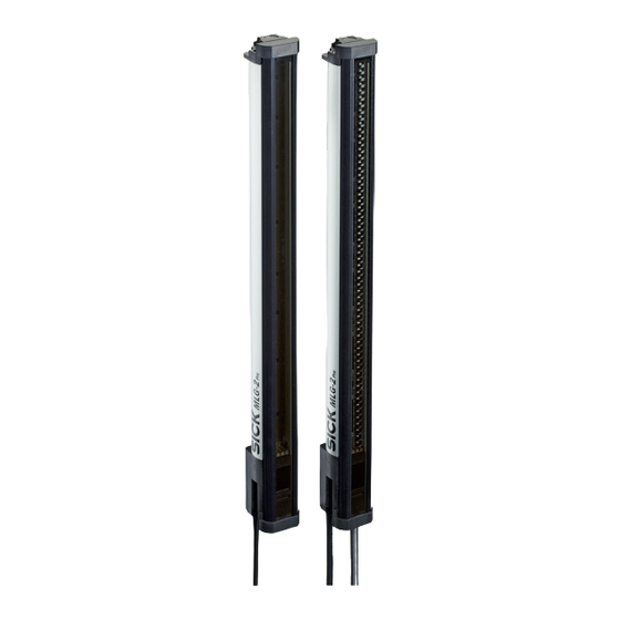
SICK MLG-2 Pro Operating Instructions Manual (138 pages)
Measuring automation light grid
Brand:
SICK
| Category:
Measuring Instruments
| Size: 15.05 MB
Table of Contents
Table of Contents
3
1 About this Document
7
Purpose of this Document
7
Scope
7
Target Group
7
Information Depth
7
Symbols Used
7
Abbreviations Used
8
2 Safety Information
9
Requirements for the Qualification of Personnel
9
Correct Use
9
Authorized Personnel
9
General Safety Notes
10
3 Product Description
11
Type Labels of the MLG-2 Pro
11
MLG-2 Pro Type Code
11
Type Label of Sender
11
Type Label of Receiver
11
Example of an MLG-2 Pro Type Code
11
Meaning of the Positions in the Type Code
11
Monitoring Height
12
Monitoring Height [MM]
12
Combinations of MLG-2 Pro Inputs and Outputs
13
Optical Properties
13
MLG-2 Pro Preconfigurations
13
Possible Combinations of MLG-2 Pro Inputs and Outputs
13
Sensing Range and Minimum Detectable Object Length
13
Preconfiguration of MLG-2 Pro with I/O Combination B (See Table
13
Preconfiguration of MLG-2 Pro with I/O Combination I (See Table
14
Preconfiguration of MLG-2 Pro with I/O Combination R (See Table
14
MLG-2 Product Properties
15
Setup and Function
15
MLG-2 Pro Device Components
15
Pro
15
Measurement Principle
16
Synchronizing the MLG-2
16
Beam Separations and Monitoring Height
16
Detection Area of the MLG-2
16
Teach-In
17
Schematic Depiction of Available Beam Separations (MM)
17
Maximum Monitoring Heights
17
Beam Blanking
18
Detection Area with Beams Blanked
18
Sensing Ranges
19
Scan Time
19
Limiting Range
19
Response Time, Minimum Presence Time and Reproducibility of the MLG-2
20
Scan Time with Cross-Beam Function
20
Standard Scan Method
20
Scan Time in Relation to the Number of Beams
20
Scan Time with High-Speed Scan on the MLG-2
21
Cross-Beam Function
21
High-Speed Scan
21
Beam Separation and Minimum Detectable Object
22
Minimum Detectable Object with Parallel-Beam Function
22
Minimum Detectable Object
22
Minimum Detectable Object in Relation to the Beam Separation of the MLG-2
22
Minimum Detectable Object Length
23
Minimum Detectable Object Length with the MLG-2
23
Minimum Detectable Object with Cross-Beam Function
24
Cross-Beam Function
24
Minimum Detectable Object with Cross-Beam Function on the MLG-2
24
Minimum Detectable Object with High Measurement Accuracy from the MLG-2
25
Minimum Detectable Object Size with High Measurement Accuracy
25
Minimum Detectable Object Length with High Measurement Accuracy
25
Operating Reserve
26
Operating Reserves on the MLG-2
26
MLG-2 Operating Modes
26
Standard Operating Mode
27
Transparent Operating Mode
27
Dust- and Sunlight-Resistant Operating Mode
27
Interfaces
28
Output of Measurement Data (Raw Data)
28
Status of the Beams
28
Example Status for an MLG-2 with 32 Beams
28
Example Status for the Run-Length Code of an MLG-2 with 32 Beams
28
Preliminary Evaluation
29
Configurable Applications of the MLG-2 Pro
29
Example Run-Length Code with the First Beam Blocked
29
Configurable Applications for Switching Outputs
30
Configurable Applications for Analog Outputs
30
Display and Operating Elements
31
Sender
31
Receiver
31
Leds on the Sender
31
Leds on the Front Side
32
Control Panel of the MLG-2 Pro
32
Inputs
33
Switching Inputs on the MLG-2 Pro Receiver
33
Test Input on the Sender
33
Application Examples
33
Application Examples for the MLG2
33
Application Examples for the MLG-2
33
Start and End Detection
33
Detection of Transparent Objects
33
Detection of Small Objects
34
Traffic Applications
34
Volume Measurement
34
Contour Measurement
34
4 Mounting
35
Scope of Delivery
35
Recommended Mounting Arrangements
35
Mounting with Light in Opposite Directions
35
Placement with Light in Opposite Directions
35
Mounting with Light in the same Direction
36
Distances When Light Is in the same Direction
36
Graph, Distances When Light Is in the same Direction
37
Placement of Two Light Grids at Right Angles
38
Graph, Distances When Light Is in the same Direction (XZ)
38
Minimum Distance from Reflective Surfaces
39
Graph, Minimum Distance from Reflective Surfaces
39
Mounting Procedure
40
Mounting the Quickfix Bracket
40
The Sender and Receiver Are Aligned Incorrectly
40
Mounting the Flexfix Bracket
41
Mount Quickfix Bracket to a Profile Frame
41
Mounting the Flexfix Bracket on a Profile Frame
42
Inserting the MLG-2 in the Flexfix Brackets
42
5 Electrical Installation
43
MLG2 Pro Electrical Installation
43
Overcurrent Protection
43
Pin Assignment, MLG-2 Pro Sender
44
Pin Assignment, MLG2 Pro Receiver, Ethernet
44
Pin Assignment, I/O, MLG2 Pro Receiver, with 4 × Q
44
Pin Assignment, I/O, MLG2 Pro Receiver, with QA
45
Pin Assignment, I/O, MLG2 Pro Receiver, with RS-485
45
T-Distributor for MLG2 Pro Connection
46
T-Distributor Connection
46
T-Distributor for Sender, Receiver, PLC
47
Pin Assignment of the PLC Connection
47
T-Distributor for Sender, Receiver, IO-Link Master
48
Pin Assignment of the IO-Link Master Connection
48
T-Distributor for Sender, Receiver, Existing MLG Connection
49
Pin Assignment of the Existing MLG Connection
49
6 Commissioning
50
Mechanical Alignment of Sender and Receiver
50
Alignment with the Quickfix Bracket
50
Alignment and Teach-In
51
MLG-2 Pro
51
Alignment with the Flexfix Bracket
51
Rotate the Receiver Once
51
Control Panel of the MLG-2 Pro
52
7 Configuration with SOPAS ET
53
Preparation
53
Installing the Software
53
Device Selection
53
SOPAS ET Interface
54
Device Selection, Operating Mode and User Level
54
System Boundaries, Status, and Interfaces
55
SOPAS ET Interface
55
Display of the System Boundaries
55
Wizards
56
Status Display for Inputs and Outputs
56
Display of the Process Quality
57
Basic Functions and Status of the Output
58
Representation of the Detection Area
59
Detection Area - Simulation
59
Combining Beams into Zones
59
Using Beams for Object Recognition
60
Using Beams for Height Classification
60
Using Beams to Classify the Object Position
61
Blanking Beams
61
Blanked Beams
61
Expandable Menus
62
Rotate the MLG-2 Display
62
Display of the MLG-2 Rotated
62
Expandable Menus for Configuration
63
Effect of the Output Configuration on the Status Indicator
63
System Settings
64
System Settings for the User Levels EASY and EXPERT
64
Effects of the Performance Options on the System Boundaries
64
System Settings for the EXPERT User Level
65
I/O Configuration
65
Beam Numbering
65
Measuring and Diagnostic Functions for Switching Outputs
66
Height Classification
67
Example Representation of the Outer Dimension
67
Settings for the Height Classification
68
Setting the Height with the Mouse
68
Object Recognition
69
Beams Highlighted in Color in the Simulation
69
Object Recognition, Static
70
Object Recognition, Dynamic
70
Object Detection/Object Width
71
Object Recognition with Tolerance
71
Object Detection/Object Width
72
Setting the Object Size with the Mouse
72
Hole Detection/Hole Size
73
Object Detection of Consecutive Objects
73
Hole Detection/Hole Size
74
Setting the Hole Size with the Mouse
74
Outside/Inside Dimension
75
Detection of Consecutive Beams
75
Measurement of the Outside Dimension
76
Measurement of the Inside Dimension
76
Setting the Outside Dimension with the Mouse
76
Classification of an Object Position
77
Classification of the Object Position - Greater than or Equal to Object Center
77
Classification of the Object Position - Less than or Equal to Object Center
77
Classification of a Hole Position
78
Classification of the Object Position - Equal to Object Center
78
Setting the Object Position with the Mouse
78
Classification of the Hole Position - Greater than or Equal to Hole Center
79
Classification of the Hole Position - Less than or Equal to Hole Center
79
Classification of the Hole Position - Equal to Hole Center
79
Diagnostics
80
Measuring and Diagnostic Functions for Analog Outputs
80
Setting the Hole Position with the Mouse
80
Object Height Measurement
81
Hole Detection
81
Settings for Object Height Measurement
81
Object Detection
82
Measuring the Outer or Inner Dimension
82
Measurement of the Outside Dimension
82
Measurement of the Inside Dimension
82
Measurement of the Object Position
83
Measurement of the Hole Position
83
Diagnostic Functions
83
Advanced Settings for the Outputs
84
Examples of the Effect of a Configured Minimum Pulse Width
84
Zones
85
Zone Measuring" Function
85
Measuring Within Zones
85
SOPAS ET Beam Window - Combining Beams into Zones
86
Data Output Via the Interfaces
87
RS485 - Data Transmission Format
87
SOPAS ET - Assigning an Application and Zone to an Output
87
RS485 - Transmission Mode
88
RS485 and IO-Link - Data Transmission Content
88
Data Transmission Format
88
Transmission Mode Via RS485
88
Available Functions
89
Selected Functions
89
Sorting Selected Functions
89
Removing Selected Functions
89
Teach-In
90
Simulation of Data Contents
90
Teach-In Successful
90
Teach-In Failed
91
Teach-In Quality
91
Example of the Blanking of Blocked Beams
92
Example of Blanking Made Beams
92
Performance Options
93
Performance Options for Standard Operating Mode and Dust- and Sunlight-Resist- Ant Operating Mode
93
Performance Options for Transparent Operating Mode
94
Cross Beam" Function
96
Illustration of the Measuring Object
96
Left: "Cross Beam Switching", Right: "Cross Beam Measuring
96
SOAPS ET - Activating Cross Beam Switching Mode
97
SOAPS ET - Activating Cross Beam Measuring Mode
98
SOAPS ET, Beam Window - "Cross Beam Measuring" Display
98
Energy Options (Only in the EXPERT User Level)
99
Beam Evaluation
99
Blocked Beams Hold (BBH)" Evaluation Mode
99
Energy Options
99
SOPAS ET - "Blocked Beams Hold (BBH)" Function
100
Lost Beams Hold (LBH)" Evaluation Mode
101
SOPAS ET - "Lost Beams Hold (LBH)" Function
101
Simulation
102
Add Simulation Object
102
Determine the Shape of the Simulation Object
102
Beam Monitor (Only in the EXPERT User Level)
103
Determine the Size of the Simulation Object
103
Start Simulation
103
Simulation Object in Simulation Area
103
Function Programming (in the EXPERT User Level)
104
Beam Status
104
Function Programming
106
Beam Functions
107
Beam Functions for Preliminary Evaluation
107
MLG-2 Configuration with the Internal Web Server
108
Interface of the Integrated Web Server
108
8 IO-Link
110
Configuration Via Acyclic Service Data
110
Data Storage (IO-Link)
110
Output of Process Data from the MLG-2 Pro
110
Data Output of the Beam Status in the Run-Length Code
110
Data Output of the Binary Beam Status
111
User-Defined Data Output
111
9 Rs-485
112
Payload
112
User-Defined Data Output
112
Content of the System Status
112
Content of the Switching Output Statuses
112
Data Volume for the Beam Functions
113
Data Volume for the Separators
113
Transmitting the Beam Status
114
Calculation Examples for the Total Data Volume
114
10 Servicing
115
11 Troubleshooting
116
Response to Faults
116
SICK Support
116
LED Indicators and Error Indicators
116
LED Indicators on the Sender
116
LED Indicators on the Receiver
116
Advanced Diagnostics on the MLG-2
117
Leds on the MLG-2 Pro Control Panel
117
12 Decommissioning
118
Disposal
118
Returns
118
13 Technical Data
119
Data Sheet
119
Data Sheet - General Data
119
Data Sheet - Electrical Specifications
119
Data Sheet - Inputs
120
Data Sheet - Outputs
120
Data Sheet - Ethernet Interface
120
Data Sheet - RS-485 Interface
120
Data Sheet - IO-Link Interface
120
Data Sheet - Technical Measurement Specifications
121
Diagrams
122
Response Time and Minimum Presence Time Without High-Speed Scan
122
Graph, MLG-2 Pro Response Time and Minimum Presence Time
122
Minimum Sensing Range with Cross-Beam Function
122
Response Time and Minimum Presence Time During High-Speed Scan with 2,5 MM Resolution
123
Response Time and Minimum Presence Time During High-Speed Scan with up to 3.5 M Sensing Range
123
Response Time and Minimum Presence Time up to 2 M Sensing Range
123
Response Time and Minimum Presence Time up to 3.5 M Sensing Range
123
Response Time and Minimum Presence Time During High-Speed Scan with up to 8.5 M Sensing Range
124
Minimum Detectable Absorption
124
Response Time and Minimum Presence Time up to 8.5 M Sensing Range
124
Minimum Detectable Absorption Required for Devices with 2 M, 5 M and 8.5 M Sensing Range
124
Dimensional Drawings
126
MLG-2 Pro Dimensional Drawing
126
Pro (MM) Dimensional Drawing
126
Measurement Tables
127
Monitoring Height (MM)/Number of Beams
127
Distance from MLG-2 Edge to First Beam
127
14 Ordering Information
128
15 Accessories
129
Accessory Part Numbers
129
16 Annex
132
Compliance with EU Directive
132
17 List of Figures
133
18 List of Tables
136
Advertisement
Advertisement
Related Products
SICK MLG-2 Prime
SICK MCS100E
SICK MARSIC300
SICK MARSIC200
SICK MARSIC280
SICK MERCEM300Z
SICK MOC3ZA
SICK MWS120
SICK MLG
SICK WebChecker MLG-2
SICK Categories
Accessories
Security Sensors
Measuring Instruments
Scanner
Barcode Reader
More SICK Manuals
Login
Sign In
OR
Sign in with Facebook
Sign in with Google
Upload manual
Upload from disk
Upload from URL