Sign In
Upload
Manuals
Brands
Servomex Manuals
Measuring Instruments
2700
Servomex 2700 Manuals
Manuals and User Guides for Servomex 2700. We have
3
Servomex 2700 manuals available for free PDF download: Installation Manual, Quick Start Manual
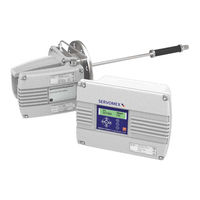
Servomex 2700 Installation Manual (117 pages)
Brand:
Servomex
| Category:
Analytical Instruments
| Size: 4.31 MB
Table of Contents
Table of Contents
5
Introduction
9
Warnings, Cautions and Notes
9
Scope of this Manual
9
General Safety Information
10
Hazardous Area Approval and Certification
11
Unpacking
11
Analyser Overview
13
Overview
13
Figure 1 Analyser Sensor Head and Control Unit Overview
13
Sensor Head Description
14
Control Unit Description
14
Sample Flow Alarm
14
Installation of Sensor Head and Probe Tube
15
Installation Location
15
Figure 2 - Sensor Head Mounting Orientation
15
Figure 3 - Protect from Radiant Heat Sources and the Sun
16
Table 1. Sensor Head Operating Environment
17
Figure 4. Sensor Head Dimensions (Typical)
19
Flange Mounting Arrangements
20
Table 2. Sensor Head Adaptor Flange Kits
22
Figure 5. Adaptor Flange Installation
23
Figure 6. High Temperature Stand-Off Flange Installation
24
Figure 7. Thermal Spacer Installation
26
Sample Probe Installation
28
Figure 8. Probe Retention Flange Installation
28
Table 3. Sample Probe Part Numbers
30
Figure 9. Sample Probe and Filter Construction
31
Figure 10. Supported Probe Construction
32
Figure 11. Probe Support Tube Installation
34
Calibration and Utilities Supplies
35
Electrical Installation
38
Figure 12. Sensor Head Terminal Enclosure Detail
41
Table 4. Sensor Head Electrical Power Connections
41
Atex/Iecex Special Instructions for Hazardous Areas
42
Figure 13. Typical Sample Arrangement
44
Figure 14. PCS Connections
45
North America Special Instructions for Hazardous Areas
46
Table 5 - Purge Control System Parameters
46
Installation of Flow Alarm Relay Box
50
Installation Location
50
Table 6. Flow Alarm Relay Box Operating Environment
50
Figure 15. Flow Alarm Relay Box Installation
51
Electrical Installation
52
Figure 16. Flow Alarm Relay Box Terminals
52
Table 7. Relay Box Terminal Information
52
Table 8. Relay Contact Specification
53
Table 9. Flow Alarm Relay Box Terminals - DIRECT Mode
53
Table 10. Flow Alarm Relay Box Terminals - INVERSE Mode
53
Figure 17. Flow Sensor Signal Amplifier Board
55
Table 11. Flow Sensor Signal Amplifier Board Terminal Information
55
Installation of Control Unit
58
Installation Location
58
Table 12. Control Unit Operating Environment
59
Figure 18. Control Unit Installation
60
Electrical Installation
61
Table 13. Control Unit Electrical Power Voltage Selection
63
Figure 19. Control Unit Enclosure Detail
64
Table 14. Control Unit Electrical Power Connections
65
Table 15. Relay Output Connections
66
Table 16. Analogue Output Connections
66
Enclosure Purge Connection
67
Table 17. User Remote Dry Contact Inputs
67
Initial Startup Procedure
70
Gases Required
70
Visual Inspection
70
Table 18. Gas Requirements
70
Initial Power up
71
Analogue Output Span Setup
71
Sensor Head Sample Flow Adjustment
72
Combustibles Sensor Zero Adjustment
72
Sensor Calibration
72
Flow Alarm Calibration
73
Figure 20. Flow Alarm Relay Box Components
73
Maintenance and Spares
77
Maintenance
77
Replacing Fuses
78
Preventative Maintenance
78
Spare Parts
79
Table 19. Control Unit - Description
79
Table 20. Sensor Head - Description
80
Table 21. Sample Probes - Description
82
Table 22. Manuals - Description
83
Table 23. Flow Alarm Relay Box Spares
83
Technical Specification
84
Oxygen Measurement Performance
84
Combustibles Measurement Performance
84
Table 24. Oxygen Measurement Performance
84
Table 25. Combustibles Measurement Performance
84
Flow Alarm Performance
85
Table 26. Flow Alarm Performance
85
Analyser Inputs and Outputs
86
Table 27. Analyser Inputs and Outputs Summary
86
Physical
87
Materials in Contact with Sample
88
Hazardous Area Classification
88
Table 28. Physical Specification
88
Table 29. Materials in Contact with Sample
88
Sensor Head Purge Certification Labels
91
Figure 21. Leakage Compensation Label
91
Table 30. Hazardous Area Classification
91
Figure 22. Continuous Flow Label
92
Appendix A - Interconnecting Wiring Schedules
94
Table 31. Interconnecting Cable Requirements
94
Table 32. Recommended Cables and Suppliers
95
Figure 23. Oxygen Sensor Only Interconnection Wiring Schematic
96
Table 33. Oxygen Sensor Only Interconnection Wiring
97
Figure 24. Combustibles Only Interconnection Wiring Schematic
98
Table 34. Combustibles Only Interconnecting Wiring
99
Figure 25. Dual Sensor Interconnection Wiring Schematic
100
Figure 26. Flow Alarm Interconnection Wiring Schematic
102
Table 35. Dual Sensor Interconnecting Wiring
102
Table 36. Flow Alarm Interconnection Wiring Schematic
103
Appendix B - Compliance and Standards Information
104
Appendix C - Product Disposal / Applicability of the Waste Electrical and Electronic Equipment (WEEE) Directive
106
Appendix D - REACH Regulation
108
Appendix E - North American - Hazardous Area Installation Drawing
110
Advertisement
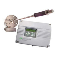
Servomex 2700 Installation Manual (60 pages)
COMBUSTION GAS ANALYSERS
Brand:
Servomex
| Category:
Measuring Instruments
| Size: 1.08 MB
Table of Contents
Table of Contents
3
Introduction
5
Warnings, Cautions and Notes
5
Scope of this Manual
5
General Safety Information
7
Hazardous Area Approval and Certification
8
Unpacking
9
Servomex 2700 Overview
11
Overview
11
Figure 1 Servomex 2700 Sensor Head and Control Unit Overview
11
Sensor Head Description
12
Control Unit Description
12
Installation of Sensor Head and Probe Tube
13
Installation Location
13
Table 1 Sensor Head Operating Environment
14
Figure 2 Servomex 2700 Sensor Head Dimensions (Typical)
15
Flange Mounting Arrangements
16
Standard Installation
16
Weld-On Flange Installation
17
Adaptor Flange Installation
17
Table 2 Sensor Head Adaptor Flange Kits
17
Adaptor Flange Installation
18
Figure
18
High Temperature Stand-Off Installation
19
Figure 4 High Temperature Stand-Off Flange Installation
20
Thermal Spacer Installation
21
Figure 5 Thermal Spacer Installation
22
Probe Retention Flange Installation
23
Figure 6 Probe Retention Flange Installation
24
Sample Probe Installation
25
Open-Ended and Unsupported Filtered Metal Probe Installation21
25
Open-Ended Ceramic Probe Installation
25
Table 3 Sample Probe Part Numbers
26
Figure 7 Sample Probe and Filter Construction
27
Figure 8 Supported Probe Construction
28
Supported Probe Installation
29
Figure 9 Probe Support Tube Installation
31
Calibration and Utilities Supplies
32
Electrical Installation
33
Table 4 Sensor Head Electrical Power Connections
34
Figure 10 Sensor Head Terminal Enclosure Detail
35
Figure 10
35
Installation of Control Unit
37
Installation Location
37
Table 5 Control Unit Operating Environment
38
Figure 11 Control Unit Installation
39
Electrical Installation
40
Table 6 Control Unit Electrical Power Voltage Selection
41
Figure 12 Control Unit Enclosure Detail
42
Enclosure Purge Connection
43
Table 7 Control Unit Electrical Power Connections
44
Table 8 Relay Output Connections
44
Table 9 Analogue Output Connections
45
Table 10 User Remote Dry Contact Inputs
45
Initial Startup Procedure
47
Gases Required
47
Table 11 Utility Gas Sample Requirements
47
Visual Inspection
48
Initial Power up
48
Analogue Output Span Setup
49
Sensor Head Sample Flow Adjustment
49
Combustibles Sensor Zero Adjustment
49
Sensor Calibration
50
Maintenance and Servicing
51
Interconnecting Wiring Schedules
53
Table 12 Interconnecting Cable Requirements
53
Oxygen Sensor Only Interconnection Wiring Schematic
54
Table 13 Oxygen Sensor Only Interconnecting Wiring
55
Combustibles Only Interconnection Wiring Schematic
56
Table 14 Combustibles Only Interconnecting Wiring
57
Figure 15
58
Dual Sensor Interconnection Wiring Schematic
58
Table 15 Dual Sensor Interconnecting Wiring
59
Servomex 2700 Quick Start Manual (41 pages)
combustion gas analyser
Brand:
Servomex
| Category:
Measuring Instruments
| Size: 0.92 MB
Table of Contents
Product View
5
Scope of this Manual
7
About this Manual
7
Key to Figures
8
Sensor Head and Control Unit Parts List
8
Enter Key
8
Analyser Startup
9
Startup and Shutdown
9
Analyser Shutdown
10
Operating the Analyser
11
Fault Messages
12
View/Configure Functions
13
Analyser Setup
14
Setting up the Concentration Alarms
14
Setting up the Relay Outputs
15
The Possible Relay Assignments
15
Setting up the Analogue Outputs
16
Setting up a Blowback Process
17
Setting up the Real Time Clock and Date Format
18
Calibration
19
Setting a New Password
19
Setting the Auxiliary Air Option
19
Manual Calibration Procedure
20
Automatic Calibration
21
Recommended Calibration Gas
22
Setting up the Automatic Calibration Parameters
23
Service Functions
23
Software Filtration
24
Testing the Analogue Outputs
24
Testing the Relay Outputs
24
Delete History
24
Language Options
25
Routine Maintenance and Spare Parts
27
Item Description
31
Technical Specification
33
Oxygen Measurement Performance
33
Combustibles Measurement Performance
33
General Specification
34
Advertisement
Advertisement
Related Products
Servomex SERVOTOUGH LaserExact 2950
Servomex Servotough SpectraScan 2400
Servomex 2500 Series
Servomex SERVOTOUGH OxyExact 2200 Series
Servomex 2223A
Servomex SERVOTOUGH SpectraExact 2500
Servomex 01440002D
Servomex 07931001B
Servomex 1100A
Servomex 1100H
Servomex Categories
Measuring Instruments
Analytical Instruments
Transmitter
Industrial Equipment
More Servomex Manuals
Login
Sign In
OR
Sign in with Facebook
Sign in with Google
Upload manual
Upload from disk
Upload from URL