Sign In
Upload
Manuals
Brands
Sel Manuals
Monitor
2414
Sel 2414 Transformer Monitor Manuals
Manuals and User Guides for Sel 2414 Transformer Monitor. We have
1
Sel 2414 Transformer Monitor manual available for free PDF download: Instruction Manual
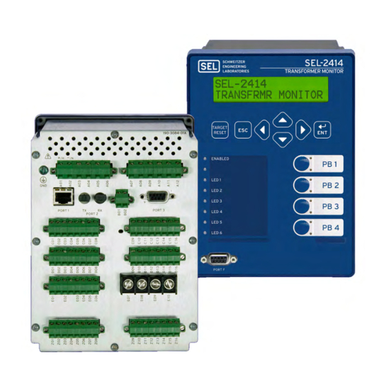
Sel 2414 Instruction Manual (362 pages)
Transformer Monitor
Brand:
Sel
| Category:
Monitor
| Size: 5.69 MB
Table of Contents
Table of Contents
3
Preface
11
Conventions
11
Typographic Conventions
11
Safety and General Information
11
Safety Information
11
Symbols
12
Environmental Conditions and Voltage Information
12
Laser/Led Emitter
13
Safety Warnings and Precautions
14
Wire Sizes and Insulation
14
Instructions for Cleaning and Decontamination
15
Technical Assistance
15
Section 1: Introduction and Specifications
17
Overview
17
Features
18
Physical
18
Monitoring
18
Automation and Control
18
Metering
19
Communications Protocols
19
Models, Options, and Accessories
19
Models
19
Options
19
Accessories
20
Applications
21
General
21
Single Monitor
22
Dual Monitor
22
Specifications
23
Section 2: Installation
29
Overview
29
Device Placement
30
Physical Location
30
Device Mounting
30
Card Configuration
31
CPU Card Communications Ports
32
Communications Card (SEL ECT EIA-232/EIA-485)
32
RTD Card (SEL ECT 10 RTD)
33
RTD/TC Card (10 RTD
33
Voltage Card (3 AVI)
34
Current/Voltage Card (3 ACI/3 AVI)
34
Current Card (4 ACI)
34
Analog Input Card (8
35
Analog Input Card (4
36
Digital Output Card (8
37
Digital Input/Output Card (4
38
Changing Cards
38
Password and SEL BOOT Jumper Selection
40
Rear-Panel Connections
41
Rear-Panel and Side-Panel Diagrams
41
Power Connections
43
Grounding (Earthing) Connections
43
Communications Ports
43
Serial Ports
43
IRIG-B Time-Code Input
44
Ethernet Port
44
Fiber-Optic Port
44
Cables
44
Digital Inputs
45
Digital Outputs
45
Analog Inputs and Outputs
45
Thermocouple Inputs
46
Thermocouple Calibration
46
RTD Inputs
47
Current Connections
47
Voltage Connections
48
Field Serviceability
50
Fuse Replacement
50
Real-Time Clock Battery Replacement
50
Section 3: Getting Started
51
Overview
51
Connecting the Device
51
AC SEL ERATOR Quickset
52
Overview
52
Installation
52
Connection Parameters
53
Checking Device Status
54
Viewing Device Information
55
Update
55
Manage Databases
55
Edit (New, Open, Read) Settings
56
File > New
56
File > Open
57
File > Read
57
Help
58
AC SEL ERATOR Quickset Graphical Logic Editor
58
AC SEL ERATOR Quickset Design Templates
58
Section 4: Logic Functions Overview
60
Logical Operators
60
Mathematical Operators
61
Function Blocks
61
General Logic Functions
62
SEL OGIC Enables
62
Latches
62
Operation
62
Power Loss
63
Settings Change
63
Latch Settings
63
Variables/Timers
63
Operation
63
Sv/Timers Set
64
Timers Reset When Power Lost or Settings Changed
64
Counter Variables
64
Math Variables
66
Output Contacts
66
SEL OGIC Control Equation Operators
67
Operator Precedence
67
Section 5: Metering and Monitoring
69
Overview
69
Metering
70
RTD Metering
70
RTD/TC Metering
71
Fundamental Metering
71
Power Measurement Conventions
72
Energy Metering
73
Maximum and Minimum Metering
73
Demand Metering
74
Thermal Demand (EDEM := THM)
75
Rolling Demand (EDEM := ROL)
75
Demand Meter Settings
76
View or Reset Demand Metering Information
76
Demand Metering Updating and Storage
76
Analog Input Metering
76
Math Variable Metering
77
Remote Analog Metering
77
Thermal Element
78
Application Description
78
Transformer Nameplate Application Description
79
Operating Characteristic
81
Temperature Inputs to the Thermal Element
82
Cooling Stage Determination
83
Thermal Element Calculations
84
Insulation Loss of Life
86
Thermal Probe Selection Settings Descriptions
88
Thermal Element Settings Descriptions
89
Thermal Alarm Limits
93
Cooling Stage N Constants
99
Thermal Element Condition
101
Thermal Monitor Reports
101
Viewing Information
101
Through-Fault Event Monitor
105
Meaning of Accumulated Through-Fault Capability
107
Through-Fault Monitor Report (TFE Command)
108
Analog Signal Profiling
109
Signal Profile Settings
109
Section 6: Settings
111
Overview
111
View/Change Settings Using the Front Panel
112
View/Change Settings over Communications Port
113
View Settings
113
Enter Settings
114
Device Settings (SET Command)
115
Transformer Settings
115
Analog Inputs
116
Analog Input Calibration Process
116
Analog Input Setting Example
117
Analog Input Settings
119
Analog Outputs
119
Internal RTD Inputs
121
External RTD Inputs
121
Universal Temperature Inputs
122
Global Settings (SET G Command)
122
General Settings
122
Event Messenger Points
123
Digital Input Configuration
124
Digital Input Debounce
125
DC Mode Processing (DC Control Voltage)
125
AC Mode Processing (AC Control Voltage)
128
Data Reset
129
Time Synchronization Source
129
Access Control
129
Voltage Ratio Correction Factor
129
SEL-2414 Settings Sheets
131
Logic Settings (SET L Command)
141
Section 7: Communications
167
Overview
167
Communications
167
Communications Ports
167
Irig
168
VDC Power Supply
168
Port Connector and Communications Cables
168
SEL-2414 Cable Connections to Communications Devices
169
Communications Protocols
170
Hardware Flow Control
170
Protocols
170
Ethernet Protocols (Port 1A, 1B)
171
Device Access
171
Change the Default Passwords
171
Access Levels
171
Access Commands (ACCESS and 2ACCESS)
172
Password Requirements
172
ASCII Commands
172
ANALOG Command (Test Analog Outputs)
172
Example 1
173
BNAMES Command (Binary Names)
174
CAL Command
174
CASCII Command (Compressed ASCII)
174
CEVENT Command (Compressed Event Report)
174
CHISTORY Command (Compressed History)
175
CMETER Command (Compressed METER)
175
COMMUNICATIONS Command
175
CONTROL Command (Control Remote Bit)
176
COUNTER Command (Counter Values)
177
CPROFILE Command (Compressed Signal Profile Values)
177
CSTATUS Command (Compressed Status)
177
CSUMMARY Command (Compressed Summary)
177
DATE Command (View/Change Date)
177
ETHERNET Command
177
EVENT Command (Event Reports)
178
FILE Command (Manage Settings Files)
178
HELP Command
178
HISTORY Command (Events List)
178
GOOSE Command
179
IDENTIFICATION Command
181
IRIG Command
181
L_D Command (Load Firmware)
181
LOOPBACK Command
182
MAC Command
182
MAP Command (Display DNP3 Maps)
183
METER Command (Metering Data)
184
MET a Analog Input Metering
184
MET RTD Metering
185
MET Temp Metering
185
MET RA Remote Analog Metering
185
MET MV Math Variable Metering
185
MET F K Fundamental Metering
185
MET Demand/Peak Demand Metering
186
MET M Maximum/Minimum Metering
186
MET E Energy Metering
186
PASSWORD Command (View/Change Passwords)
187
PING Command
188
PROFILE Command (Signal Profile Values)
188
PULSE Command (Test Outputs)
188
QUIT Command
189
SER Command (Sequential Events Recorder Report)
189
SET Command (Change Settings)
190
SHOW Command (Show/View Settings)
191
SNS Command (Displays SER Settings)
191
STATUS Command (Device Self-Test Status)
192
SUMMARY Command (Summary)
192
TARGET Command (Display Device Word Bit Status)
192
TFE (Through-Fault Event Report)
193
THE (Thermal Report)
194
TIME Command (View/Change Time)
194
TRIGGER Command (Trigger Event Report)
195
Section 8: Front-Panel Operations
197
Front-Panel Overview
197
Human-Machine Interface
198
Front-Panel Automatic Messages
198
Display Points
198
Boolean Display Point
198
Analog Display Point
199
Rotating Display
201
Local Bits
201
Contrast
202
Front-Panel Security
202
Front-Panel Access Levels
202
Access Level 2 Password Entry
203
Front-Panel Time-Out
203
Front-Panel Menus and Screens
203
Navigating the Front-Panel Menus
203
Menu Structure
204
Meter Menu
205
Events Menu
206
Targets Menu
206
Control Menu
206
Set/Show Menu
207
Status
208
Quit
208
Operation and Target Leds
208
Enabled LED
208
Programmable Leds
208
Target Leds
209
Pushbutton Leds
209
TARGET RESET Pushbutton
209
Target Reset
209
Lamp Test
210
Other Target Reset Options
210
Section 9: Analyzing Events
211
Overview
211
Event Reporting
211
Sequential Events Recorder (SER)
212
Event Reporting
212
Length
212
Triggering
212
Programmable SEL OGIC Control Equation Setting
212
TRI (Trigger Event Report) Command
212
Event Summaries
213
Event History
214
Viewing the Event History
214
Clearing
214
Event Reports
214
Filtered and Unfiltered Event Reports
215
Column Definitions
215
Example 15-Cycle Event Report
217
Sequential Events Recorder (SER) Report
219
Inputs
219
Chatter Filtering
219
SER Triggering
220
SER Aliases
220
Viewing and Clearing SER Reports
220
Example SER Report
220
Section 10: Testing and Troubleshooting
223
Overview
223
Functional Testing
223
Device Status Verification
223
Input Verification
223
Output Verification
224
Meter Verification
224
EVENT Command
224
SER Command
224
TARGET Command
224
Low-Level Test Interface
224
Using the Low-Level Test Interface When Setting DELTA_Y := DELTA
226
Introduction
227
Required Equipment
227
Procedure
227
Phase Current Measuring Accuracy
230
Power and Power Factor Measuring Accuracy
230
Self-Test
232
Troubleshooting
235
Appendix A: Firmware and Manual Versions
237
Firmware
237
Determining the Firmware Version in Your Device
237
Instruction Manual
239
Appendix B: Firmware Upgrade Instructions
243
Step 1: Prepare Device
243
Step 2: Transfer Firmware
244
Step 3: Prepare Device
244
Step 4: Verify Device
244
IEC 61850 CID File Upgrade Instructions
245
Verify or Restart IEC 61850 Operation (Optional)
245
Appendix C: SEL Communications Processors
247
SEL Communications Protocols
247
SEL ASCII Commands
247
SEL Compressed ASCII Commands
247
Interleaved ASCII and Binary Messages
248
SEL Fast Meter, Fast Operate, Fast SER, and Unsolicited Write
248
SEL Communications Processor
249
SEL Communications Processor and Device Architecture
251
Developing Star Networks
251
SEL Communications Processor Example
253
Data Collection
253
Device Metering Data
254
Device Word Bits Information
258
Control Points
258
SEL Communications Processor to SEL-2414 Unsolicited Write Remote Analog Example
259
Setting the SEL Communications Processor
260
Setting the SEL-2414
261
Appendix Ddnp3 Communications
263
Overview
263
Objects
263
Function Codes
263
Qualifier Codes and Ranges
263
DNP3 in the SEL-2414
264
Data Access
264
Collision Avoidance
264
Transmission Control
265
Event Data
265
Time Synchronization
265
Modem Support
266
DNP3 Settings
266
Configurable Data Mapping
266
Device Profile
266
Reference Data Map
271
Default Data Map
273
Binary Inputs
274
Analog Inputs
274
Binary and Analog Outputs
274
Control Point Operation
274
Appendix E Modbus Communications
277
Overview
277
Modbus Queries
277
Modbus Responses
277
Supported Modbus Function Codes
277
Function Code Details
278
Read Discrete Output Coil Status Command
278
Read Input Status Command
278
Read Holding Register Command
279
Read Input Register Command
279
Force Single Coil Command
280
Preset Single Register Command
280
Reading Event Summary Data Using Modbus
281
Controlling Output Contacts and Remote Bits Using Modbus
281
Modbus Register Map
283
Conversion Table
307
Appendix Fiec 61850 Communications
309
Features
309
IEC 61850 Configuration
309
AC SEL ERATOR Architect
309
Logical Node Extensions
310
Protocol Implementation Conformance Statement: SEL-2414 Devices
316
MMS Conformance
316
GOOSE Services Conformance Statement
321
ACSI Conformance Statements
321
Appendix G: MIRRORED BITS Communications
327
Overview
327
Operation
327
Message Transmission
327
Message Reception Overview
328
Message Decoding and Integrity Checks
328
Channel Synchronization
329
Loopback Testing
330
Channel Monitoring
330
Settings
331
Appendix H Device Word Bits
333
Overview
333
Definitions
336
Appendix I Analog Quantities
343
Glossary
347
Index
351
SEL-2414 Transformer Monitor Command Summary
355
Advertisement
Advertisement
Related Products
Sel SEL-2414
Sel Categories
Relays
Controller
Control Systems
Control Unit
Power distribution unit
More Sel Manuals
Login
Sign In
OR
Sign in with Facebook
Sign in with Google
Upload manual
Upload from disk
Upload from URL